High efficiency tube mat solar collector having intermittently separated tubes and method for preventing damage to a solar collector

a solar collector and tube mat technology, applied in the field of high-efficiency tube mat solar collectors, can solve the problems of reducing solar energy collection capability, thermal energy loss, and proportionately worsening of energy collection capability, and achieve the effect of reducing lifting for

Active Publication Date: 2006-03-09
AQUATHERM INDS
View PDF1 Cites 7 Cited by
  • Summary
  • Abstract
  • Description
  • Claims
  • Application Information

AI Technical Summary

Benefits of technology

[0010] An advantage of the present invention is a reduction in lifting force exerted upon the mounting means securing the solar collector to its mounting location during periods of high velocity wind.
[0011] In one aspect, the present invention relates to a solar collector comprising
[0012] a plurality of hollow tubes, each tube being directly joined to an adjacent tube;
[0013] a first manifold connected to a first end of each tube;
[0014] a second manifold connected to a second end of each tube;
[0015] wherein at least two adjacent tubes are separated from one another along a portion of their length so as to form a first tube section in which adjacent tubes are separated from one another and a second tube segment in which adjacent tubes are directly joined to one another.

Problems solved by technology

This type of solar energy collector suffers from reduced solar energy collection capability in comparison to tube mat solar energy collectors due to the free and uninhibited passage of air around their absorber tube surfaces, which causes thermal energy loss due to convective cooling of the hollow tubes.
Moreover, their energy collection capability proportionately worsens with increasing wind speed.
A disadvantage of this closed absorbed section is the effect high winds can have on the solar collector, which can act as a sail.
More particularly, high winds can exert very high force on the solar energy absorber, which force is transmitted to attachment hardware such as lag screws which secure the solar collector to the roof.
Winds of sufficiently high velocity, for example, 15 miles per hour or above, can damage and even remove or otherwise destroy roof-mounted tube mat solar collectors.
However, the use of additional mounting hardware increases the cost of material and labor, and requires an undesirable increase in the number of penetrations into a homeowner's roof.

Method used


Image

  • High efficiency tube mat solar collector having intermittently separated tubes and method for preventing damage to a solar collector
  • High efficiency tube mat solar collector having intermittently separated tubes and method for preventing damage to a solar collector
  • High efficiency tube mat solar collector having intermittently separated tubes and method for preventing damage to a solar collector

Examples


Embodiment Construction

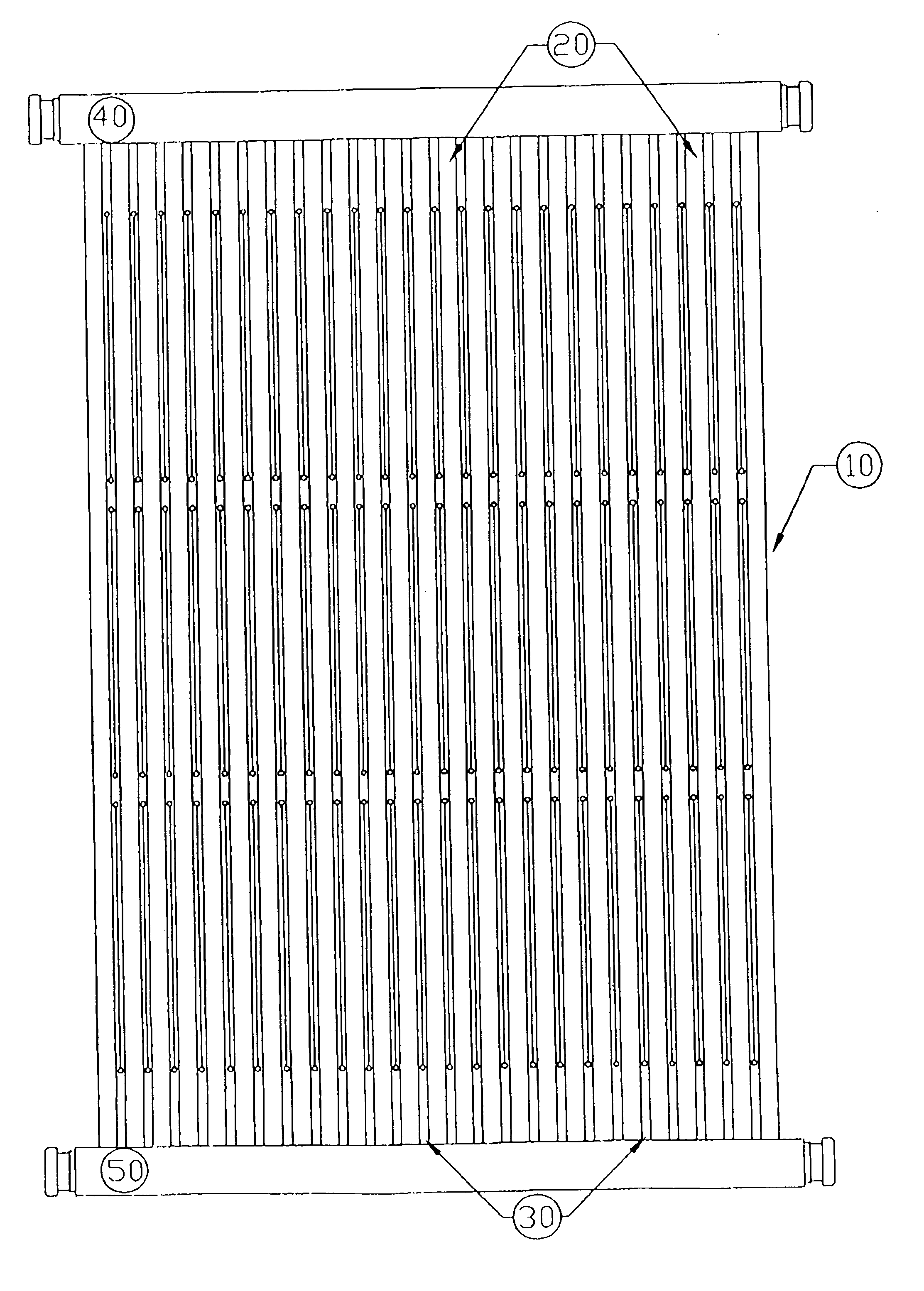
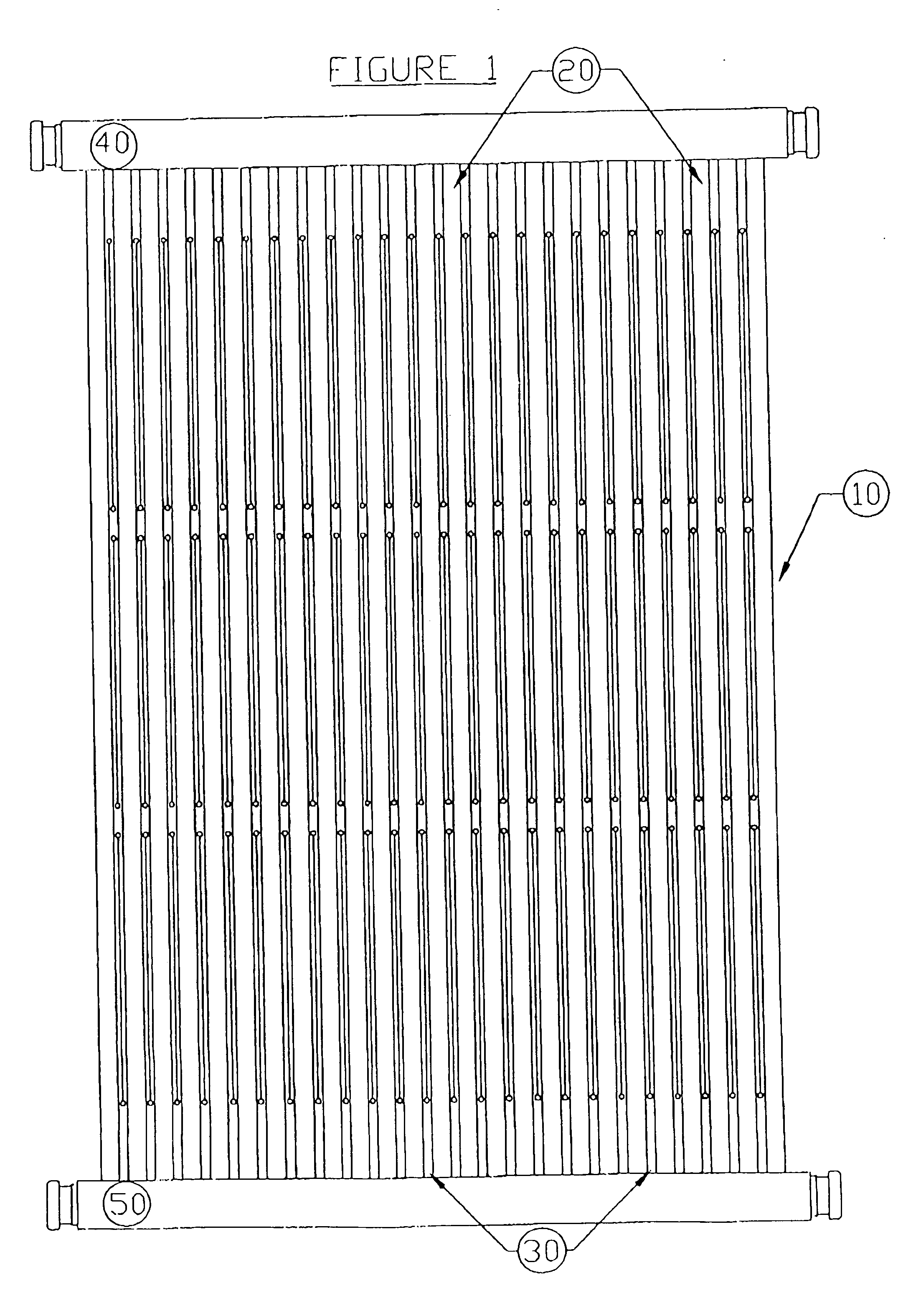
[0032] A first preferred embodiment of the solar collector of the present invention is shown in FIGS. 1-3. Tube mat 10 comprises a plurality of hollow tubes 20, with each tube 20 directly joined to an adjacent tube. By “directly joined to an adjacent tube” it is meant there is no web or other spacer material between adjacent tubes. First manifold 40 is connected to a first end of each hollow tube 20, while second manifold 50 is connected to a second end of each hollow tube 20.

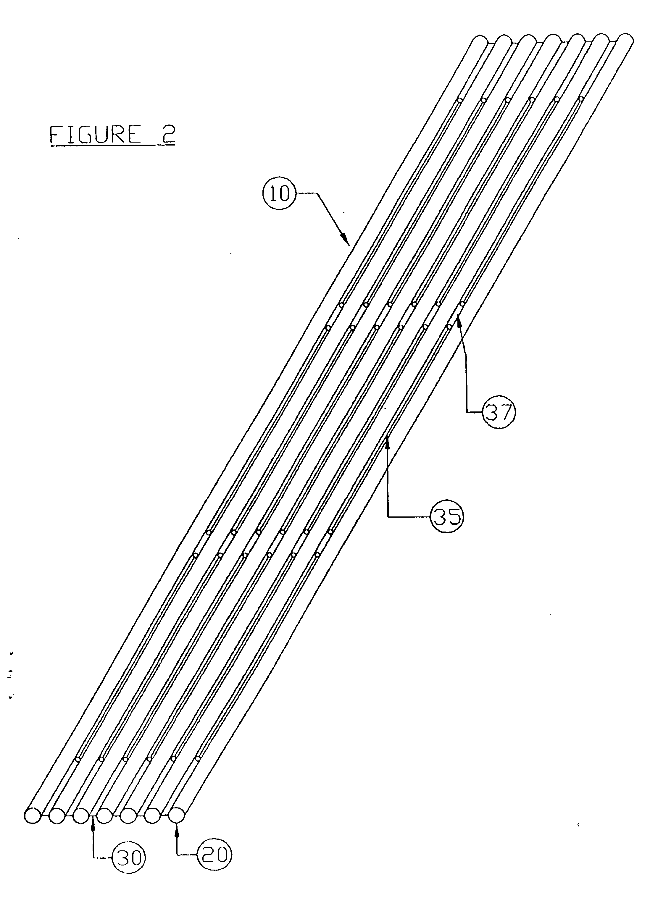
[0033] Referring to FIG. 2, adjacent tubes 20 are separated from one another along a portion of their length. The longitudinal separation has a length sufficient to permit individual tubes to move about their major axis in both the horizontal and vertical directions under high wind conditions. The width of the separation is sufficiently thin that the separation is difficult to visually observe from the ground under low to moderate wind conditions, when the solar collector is conventionally mounted on a residen...


PUM


Abstract

A solar collector including a plurality of hollow tubes, each tube directly joined, or indirectly joined by a web, to an adjacent tube; a first manifold connected to a first end of each tube; a second manifold connected to a second end of each tube; where at least two adjacent tubes are separated along a portion of their length so as to form a first section in which adjacent tubes are separated from one another and a second segment in which adjacent tubes are joined to one another. Also disclosed is a method for preventing damage to a tube mat solar collector which includes maintaining the hollow tubes of a solar collector in a substantially coplanar relationship in the absence of high wind conditions; permitting individual tubes to move about their longitudinal axis in response to high wind conditions; and returning the tubes to their longitudinal axis as the high wind conditions subside, the high wind conditions being wind of at least 15 miles per hour.

Description

[0001] This application claims the benefit of U.S. provisional patent application No. 60 / 608,152, filed Sep. 9, 2004 and U.S. provisional patent application No. 60 / 657,400, filed Mar. 2, 2005.BACKGROUND OF THE INVENTION [0002] The present invention relates to an improved solar collector having a tube construction in which the tubes of the solar collector are intermittently separated along their length. [0003] An important application of solar collectors is as part of a heating system for swimming pools. Most conventional low temperature pool heating solar collectors have an all-plastic construction which includes an extruded plastic absorber section containing hollow tubes connected to hollow manifolds on opposed absorber section ends. These absorber sections are conventionally either of tube mat or loose tube form. Tube mat collectors maintain uniform tube spacing either due to webs or spacers between adjacent hollow tubes or because adjacent tubes are connected directly to one ano...

Claims


Application Information

Patent Timeline
Patent Type & Authority Applications(United States)
IPC IPC(8): F24J2/24F24S10/70
CPCF24J2/242Y02E10/44F24J2/4638F24J2/243F24S10/72F24S10/73F24S40/85
Inventor SIZELOVE, J. DAVID
Owner AQUATHERM INDS
Why Eureka
Try Eureka