Heavy-duty pneumatic tire

Inactive Publication Date: 2006-03-09
SUMITOMO RUBBER IND LTD
View PDF5 Cites 38 Cited by
  • Summary
  • Abstract
  • Description
  • Claims
  • Application Information

AI Technical Summary

Benefits of technology

[0009] The present invention has been made in view of the above problems, and it is an object thereof to provide a heavy-duty pneumatic tire capable of effectively preventing occurrence of wrink

Problems solved by technology

Accordingly, large stress focuses and acts onto the groove bottom so that wrinkles or scars are apt to be caused on the surfaces, which remarkably worsen the external appearance of the tire.
A drawback is accordingly presented in that boundary positions between the rubber layers will not be stable.
Such

Method used


Image

  • Heavy-duty pneumatic tire
  • Heavy-duty pneumatic tire
  • Heavy-duty pneumatic tire

Examples


examples

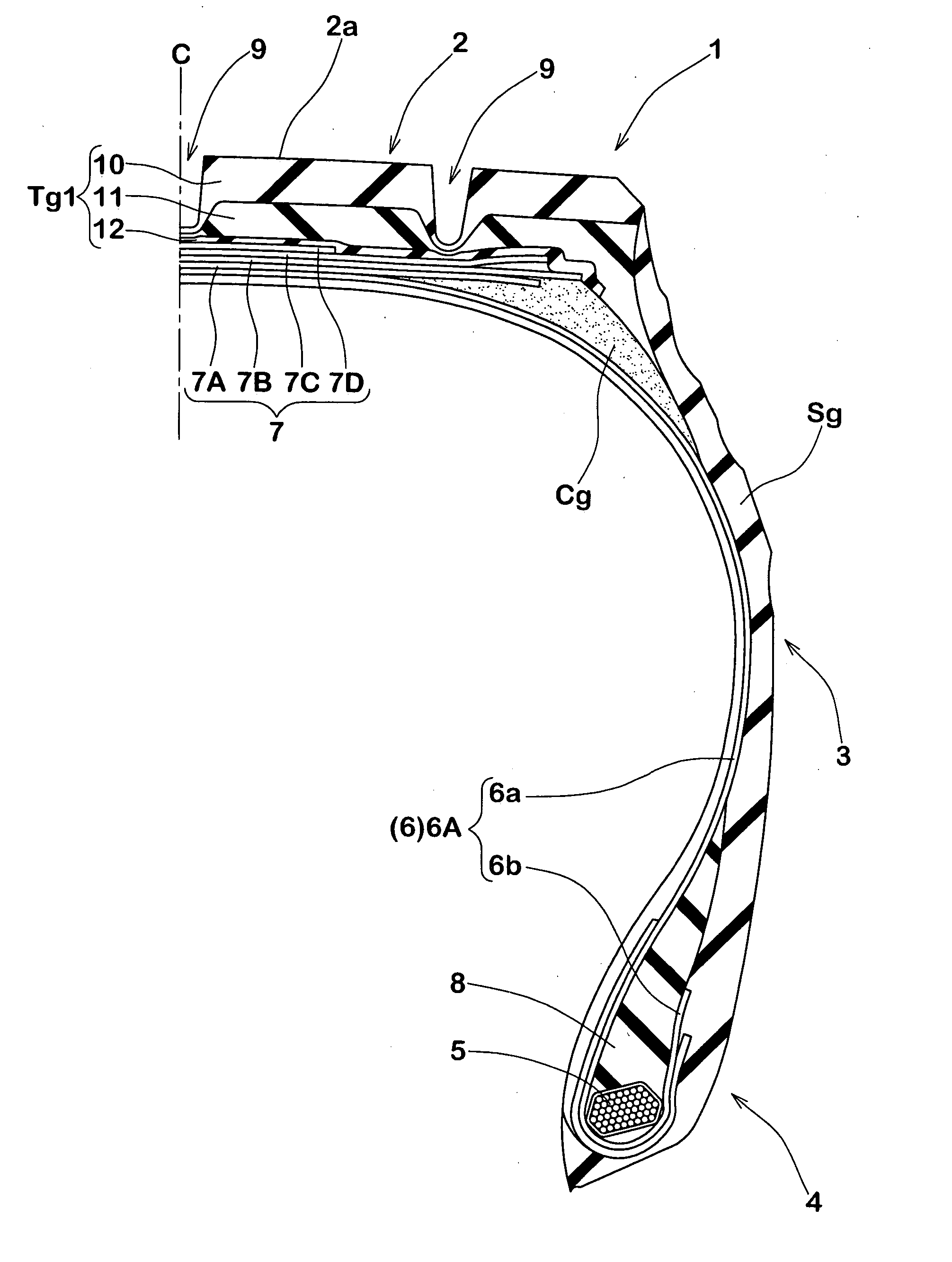
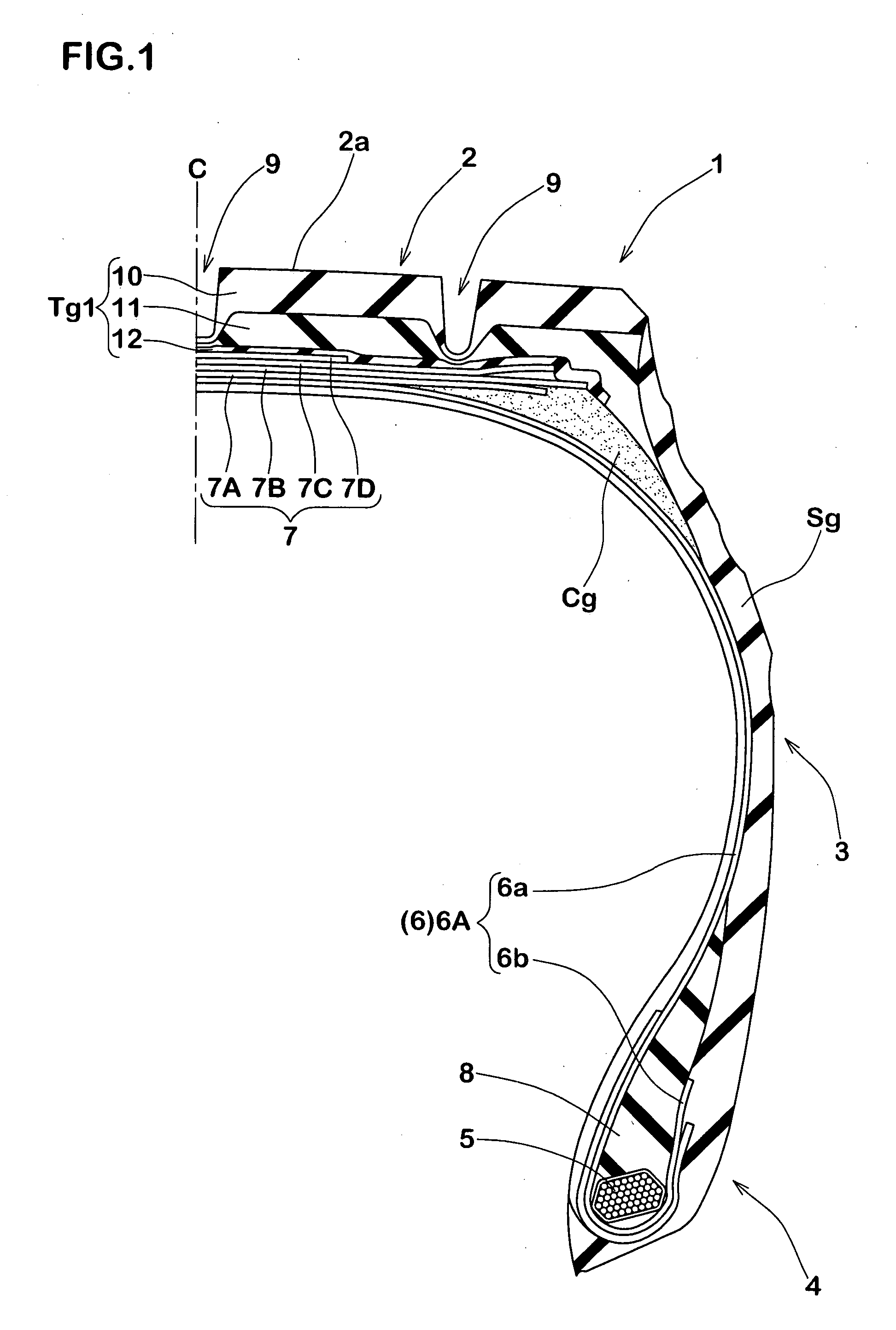
[0055] Heavy-duty pneumatic tires having the structure of FIG. 1 and a size of 11R22.5R were manufactured according to specifications of Table 1, and wear resistance, crack resistance, and thicknesses of layers of the tread rubber were evaluated. Methods of evaluation were as follows.

[0056] Each sample tire was mounted to an applicable JATMA rim (7.5022.5), filled with standard air pressure (700 kPa) and mounted to a truck loaded with freight such that applied load per tire becomes a standard load (24.5 kN) whereupon the truck was made to run over 200,000 km. As for the wear resistance, depths of main grooves were measured at 10 spots on the circumference thereof to obtain average values, and they were indicated as indices with the value of the conventional example being defined as 100. The larger the values are, the more favorable they are. As for the crack resistance, presence / absence of cracks and wrinkles on groove bottoms were checked with eyes and evaluated on the basis of th...


PUM


Abstract

An object of the present invention is to provide a heavy-duty pneumatic tire and a method for manufacturing the same capable of effectively preventing occurrence of wrinkles and cracks on groove bottoms of main grooves. The heavy-duty pneumatic tire 1 includes a carcass 6 made of steel cords and a belt layer 7. A tread rubber Tg1 thereof is comprised of a cap layer 10 disposed on an outermost side in a radial direction and is made of cap rubber having viscoelastic properties with a complex elastic modulus E*1 of 5.0 to 7.0 MPa and a loss tangent tanδ of 0.08 to 0.15, a base layer 12 having different viscoelastic properties as those of the cap rubber and that is disposed on an innermost side in the radial direction, and a middle layer 11 that is disposed between the cap layer 10 and the base layer 12 and that exhibits viscoelastic properties different from those of both. The respective layers are comprised of strip laminated bodies in which tape-like non-vulcanized rubber strips are spirally wound.

Description

BACKGROUND OF THE INVENTION [0001] The present invention relates to a heavy-duty pneumatic tire and a method for manufacturing the same with which it is possible to effectively prevent occurrence of wrinkles or cracks at groove bottoms of main grooves. [0002] Tread rubber for heavy-duty pneumatic tires that is employed in trucks and buses is usually made of hard rubber that exhibits superior wear resistance. However, in an intermediate term or later term of wear, the rigidity of land portions such as blocks or ribs is remarkably increased accompanying reductions in depths of the main grooves. Accordingly, large stress focuses and acts onto the groove bottom so that wrinkles or scars are apt to be caused on the surfaces, which remarkably worsen the external appearance of the tire. [0003] It is therefore possible to consider arranging the tread rubber formed of various types of rubber of different viscoelastic properties. FIG. 6(A) illustrates a partial sectional view of a heavy-duty ...

Claims


Application Information

Patent Timeline
IPC IPC(8): B60C11/00B60C1/00B29D30/30B29D30/60
CPCB29D30/3028B29D30/60B60C11/005B60C11/18B60C11/00B60C2011/0025
Inventor MARUOKA, KIYOTO
Owner SUMITOMO RUBBER IND LTD
Why Eureka
Try Eureka