Image compositing method and apparatus

a compositing method and image technology, applied in the field of image compositing technique, can solve the problems of limiting the range of motion of the viewer, the difficulty of arranging the sensors, and the limited range of sensors available to measure the effect of the imag

Inactive Publication Date: 2006-03-09
CANON KK
View PDF6 Cites 71 Cited by
  • Summary
  • Abstract
  • Description
  • Claims
  • Application Information

AI Technical Summary

Benefits of technology

[0009] The present invention has been made in view of the above circumstances and has an object to make it possible to arrange position and orientation sensors efficiently in an appropriate manner by visualizing measurable ranges of the sensors.

Problems solved by technology

The viewpoint position and orientation of the observer is provided as information which has six degrees of freedom, and thus sensors (position and orientation sensors) available to measure them are limited.
Consequently, arrangement of sensors limits the viewer's allowed range of motion.
Thus, when installing sensors at a site, it is a big issue how to arrange the sensors.
However, since information used by the sensors such as magnetism or light cannot be captured visually, the measurable ranges of the sensors cannot be seen visually and the sensors must be arranged by relying on experience and hunches after all.
However, sensor arrangement based on hunches may not allow a planned measurable range to be secured.
This is inefficient because of the need to install and adjust the sensors repeatedly.

Method used


Image

  • Image compositing method and apparatus
  • Image compositing method and apparatus
  • Image compositing method and apparatus

Examples


first embodiment

[0032] An example of an image compositing apparatus according to a first embodiment acquires positional information about sensors based on markers attached to the sensors, superimposes measurable ranges of the sensors on the given positions using three-dimensional CG model data, and thereby visualizes the measurable ranges of the sensors. Incidentally, the three-dimensional CG model data used to visualize the measurable ranges may be based on either sensor specifications or experience. Besides, there are no particular limits on a display method of the model data, and the model data may be either outputted as they are or outputted with their degree of transparency specified.

(Configuration of the Image Compositing Apparatus)

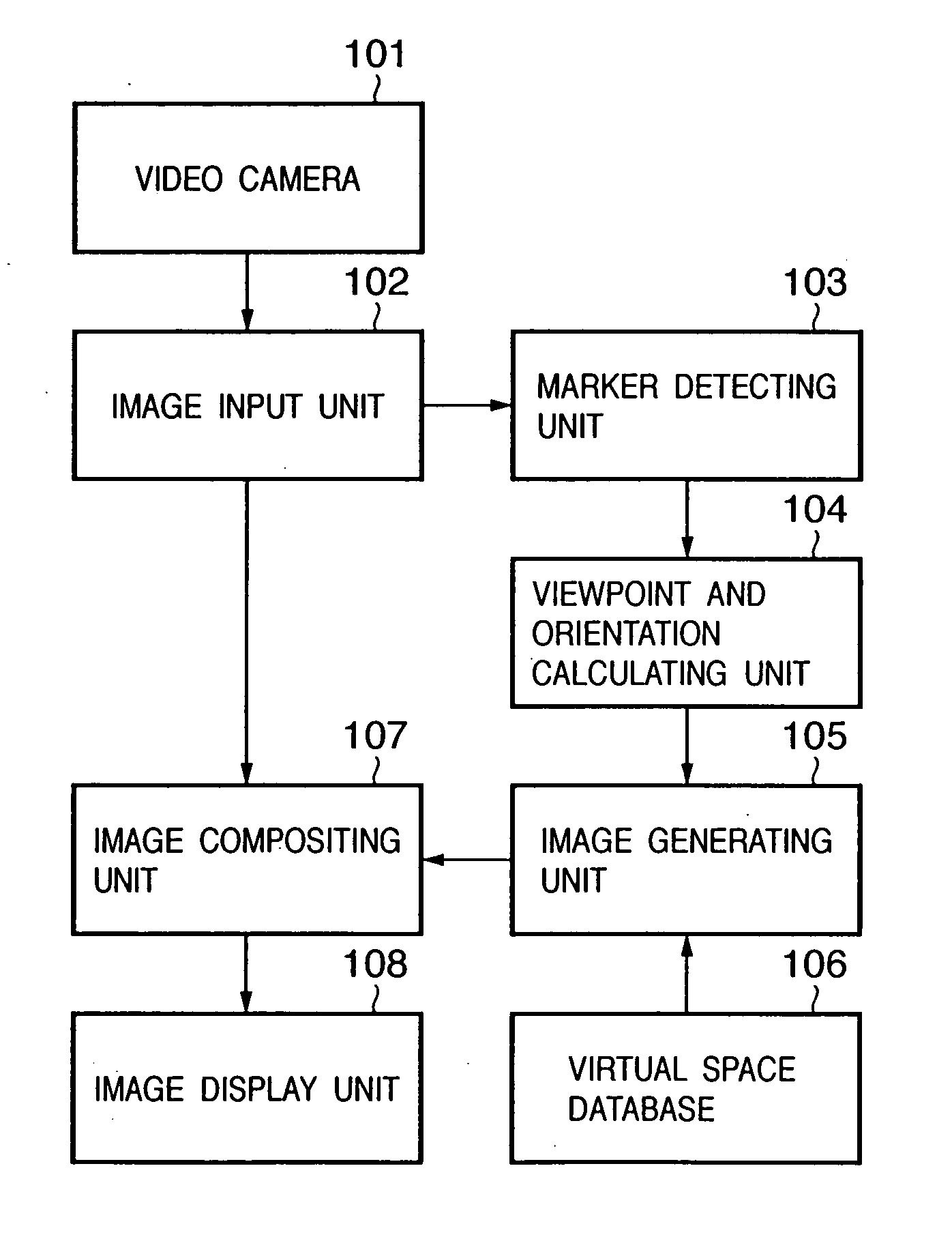
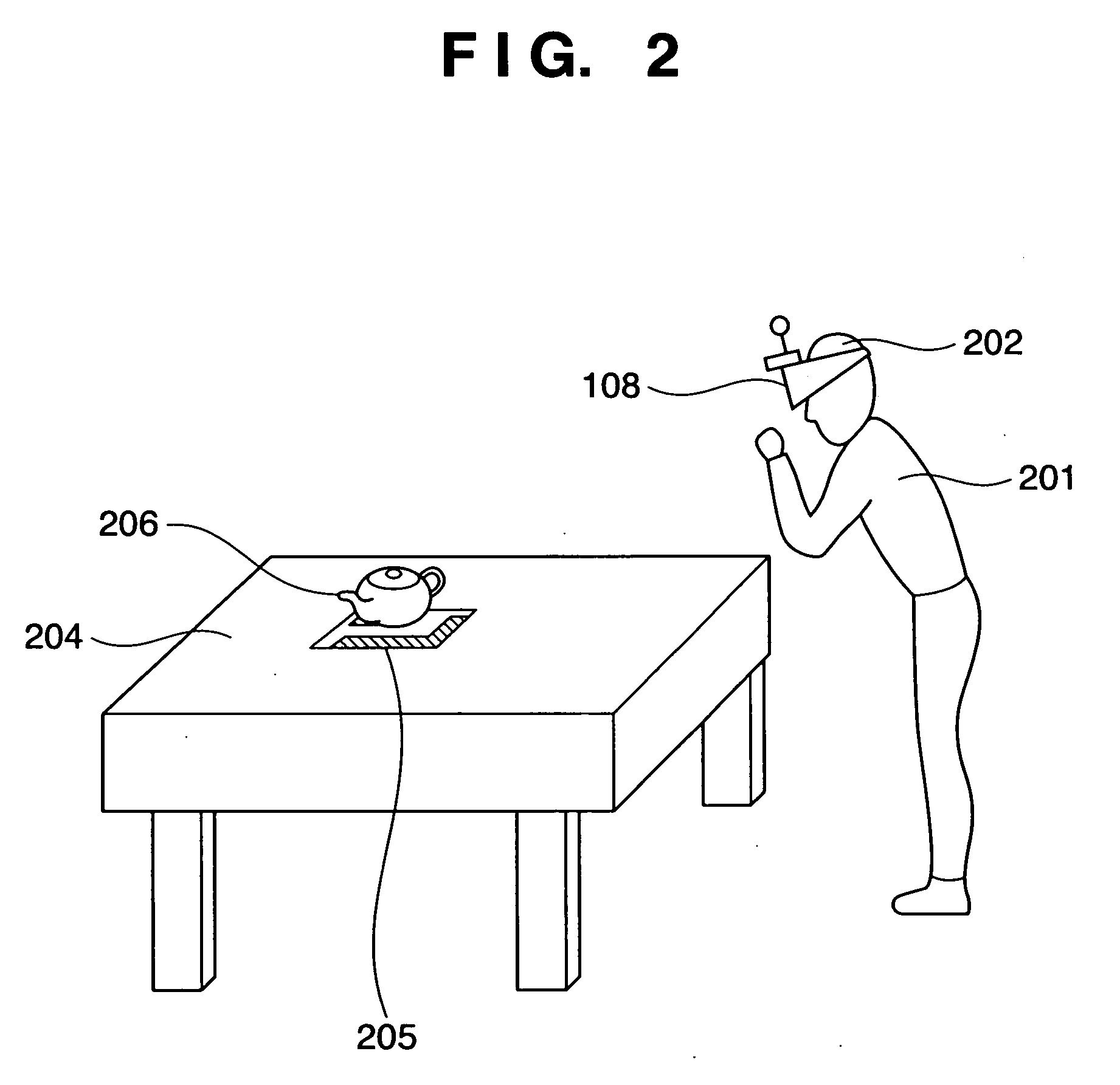
[0033]FIG. 1 is a block diagram showing a configuration example of the image compositing apparatus according to this embodiment. FIG. 2 is a diagram schematically showing a concrete equipment configuration and a sensation of mixed reality experienced by an obser...

second embodiment

[0121] An image compositing apparatus according to a second embodiment involves installing a position and orientation sensor, acquiring position and orientation information in a global coordinate system on the head of the observer based on measurement values from the actually installed position and orientation sensor, superimposing three-dimensional CG model data (prepared in advance) which represent the sensor's measurable range defined in the global coordinate system on an actually sensed image obtained from a camera installed near the line of sight of the observer, thereby visualizing the measurable range of the position and orientation sensor.

[0122] This embodiment allows the position and orientation of the user in the global coordinate system to be determined from output values of the sensor. Thus, the three-dimensional CG model data which represent the measurable range of the sensor are managed in the global coordinate system. Again, according to this embodiment, the three-di...

third embodiment

[0133] In all the above embodiments, the measurable ranges of sensors are presented to the observer. Besides, visualized measurable ranges of sensors may be presented to an operator of the image compositing apparatus. When the operator monitors operations of an observer, if the measurable ranges of sensors are visualized on an operation screen of the operator, the operator can keep track of the positional relationship between the observer and sensors' measurable ranges, and thus can lead the observer to an appropriate position.

[0134] When dynamically presenting a CG object such as the one shown in FIG. 8 to the observer, it is possible to put the CG object in a location most visible to the observer.

[0135] In this way, when presenting a sensor's measurable range to the operator, as shown in FIG. 8, an observer (registered three-dimensional CG model) and sensor's measurable range can be generated as a CG image by the image generating unit 105 using viewpoint and orientation of a thi...


PUM


Abstract

A three-dimensional computer graphics model which represents a measurable range of a position and orientation sensor is prepared in advance. A composite image is generated by superimposing an image of a virtual object which represents the measurable range of the position and orientation sensor on an actually-sensed image in real space where the position and orientation sensor is placed. The composite image, when displayed, makes it possible to visually recognize the measurable range of the position and orientation sensor.

Description

FIELD OF THE INVENTION [0001] The present invention relates to an image compositing technique for aligning and superimposing an image generated by a computer (CG: Computer Graphics) on a real-world image. BACKGROUND OF THE INVENTION [0002] There is a mixed reality (MR) technique for aligning and superimposing an image of a virtual object generated by computer graphics (hereinafter referred to as CG) on an actually-sensed image to make an observer feel as if the virtual object existed in real space (see, for example, Japanese Patent Laid-Open No. 11-84307). [0003] There are various applications of the MR technique including, for example, a medical-assistance application in which CG of internal organs is aligned and superimposed on actually-sensed images of a patient's body surface, thereby making a doctor feel as if he / she were seeing through the body, an application in which CG of assembly procedures is superimposed on actually-sensed images of a product at a factory, thereby assist...

Claims


Application Information

Patent Timeline
Patent Type & Authority Applications(United States)
IPC IPC(8): G09G5/00
CPCG06F3/011G06T7/0018G06T2207/30204G06T2207/10016G06T19/006G06T7/80
Inventor TANIMURA, KANAMEOHSHIMA, TOSHIKAZU
Owner CANON KK
Why Eureka
Try Eureka