Shroud for gauge pointer

Inactive Publication Date: 2006-03-09
SIEMENS VDO AUTOMOTIVE CORP
View PDF0 Cites 3 Cited by
  • Summary
  • Abstract
  • Description
  • Claims
  • Application Information

AI Technical Summary

Benefits of technology

[0010] The illuminated instrument assembly of the present invention provides a surface fi

Problems solved by technology

One disadvantage with illuminated pointers is that light is often transmitted from the pointer arm to undesirable locations such as toward the viewer.
Also, light may reflect onto surrounding gauge surfaces resulting in an

Method used


Image

  • Shroud for gauge pointer
  • Shroud for gauge pointer
  • Shroud for gauge pointer

Examples


Embodiment Construction

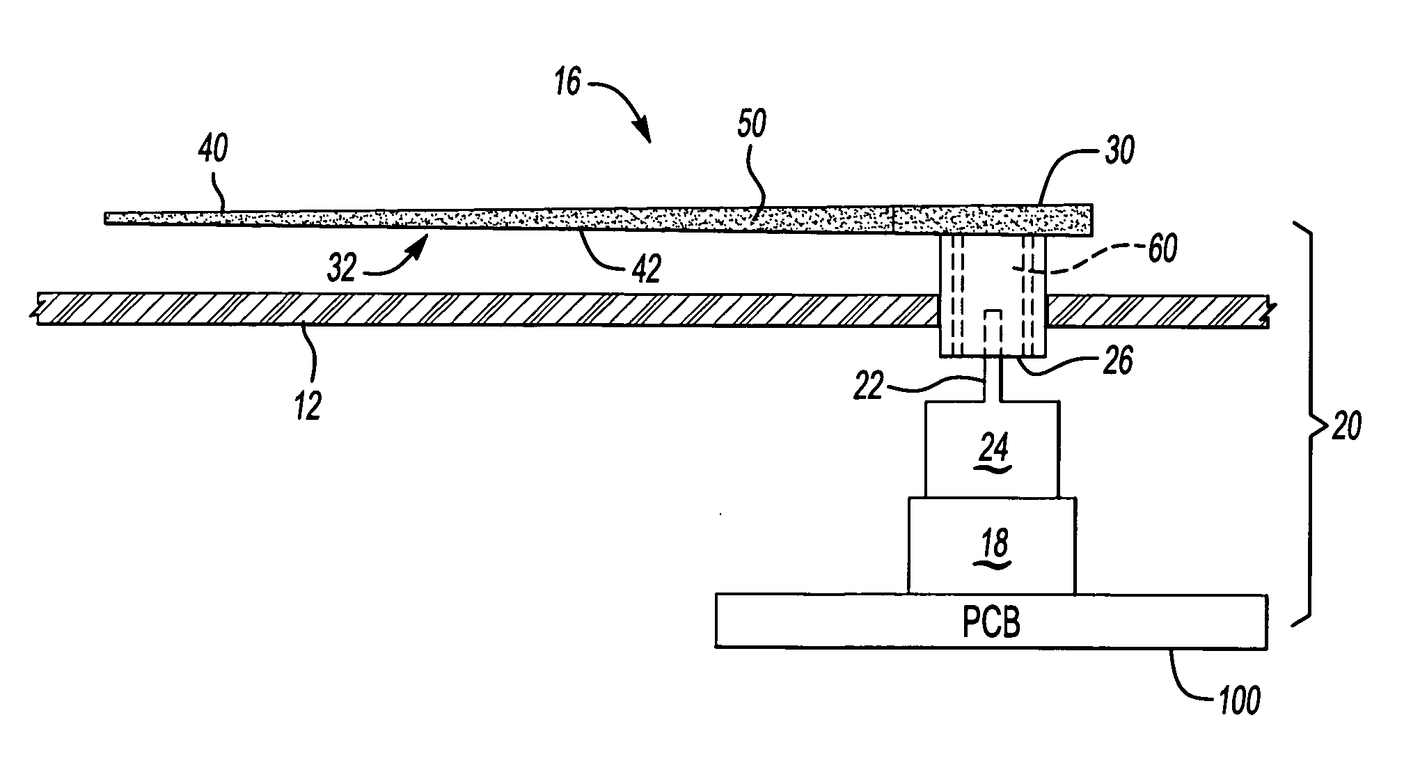
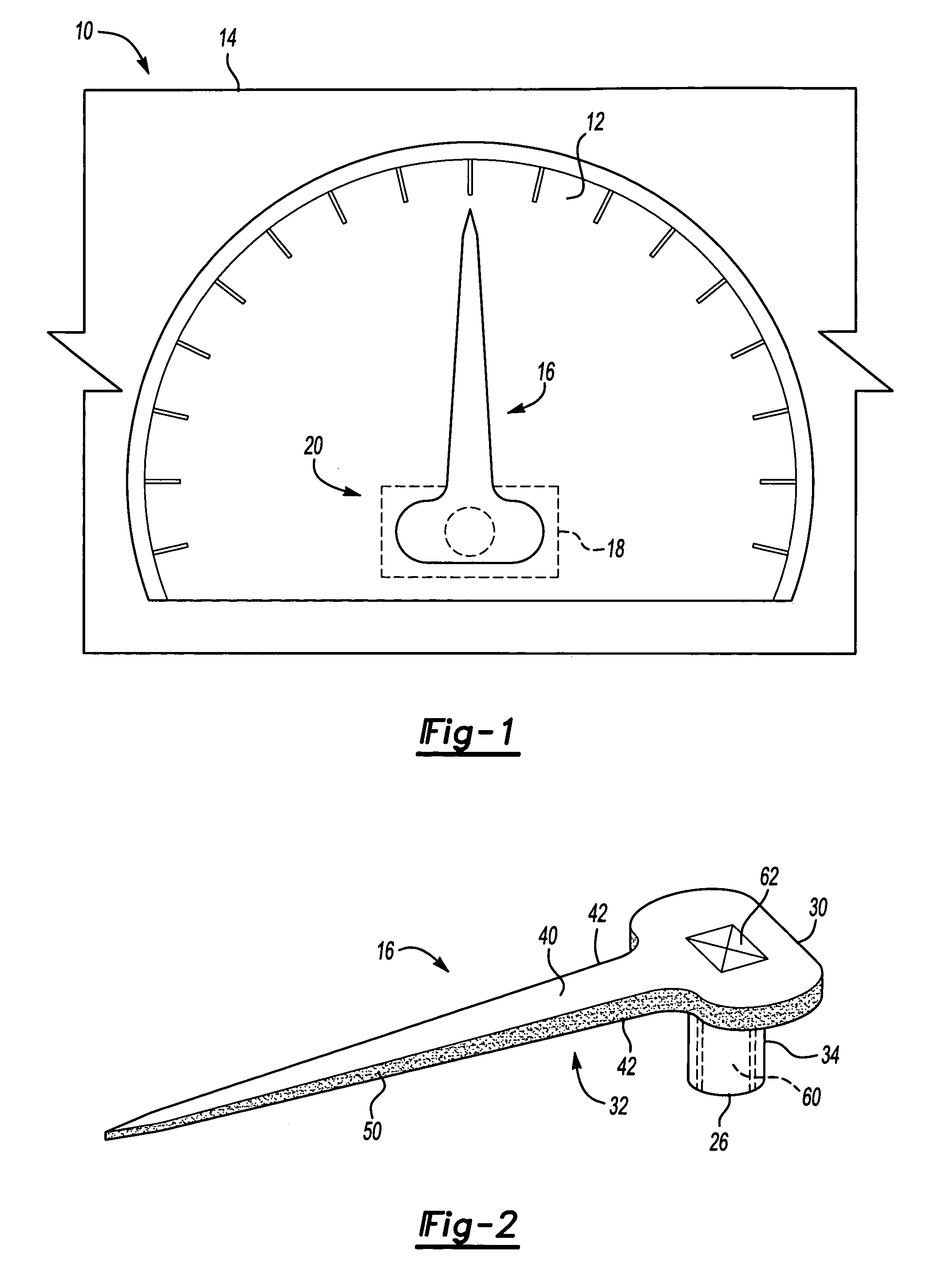
[0017] An instrument cluster 10 including at least one gauge pointer assembly 20 is shown generally in FIG. 1. The instrument cluster 10 includes a gauge 12 having a graphical image, such as a scale, for example, which is used to indicate a vehicle operating condition. The gauge 12 is mounted to a dash panel or other similar fixed vehicle structure 14. A pointer 16 is mounted for movement relative to the gauge 12 and is used to indicate the current status of the vehicle operating condition. A light source 18 is mounted behind the instrument cluster 10 and is used to illuminate at least a portion of the pointer 16 so that a vehicle operator can clearly see the vehicle operating condition. The light source 18 can illuminate the length of the pointer 16, only the tip of the pointer 16, or any portion thereof. The light source 18 is a light emitting diode [LED]. It is within the contemplation of this invention to utilize any other light source known in the art.

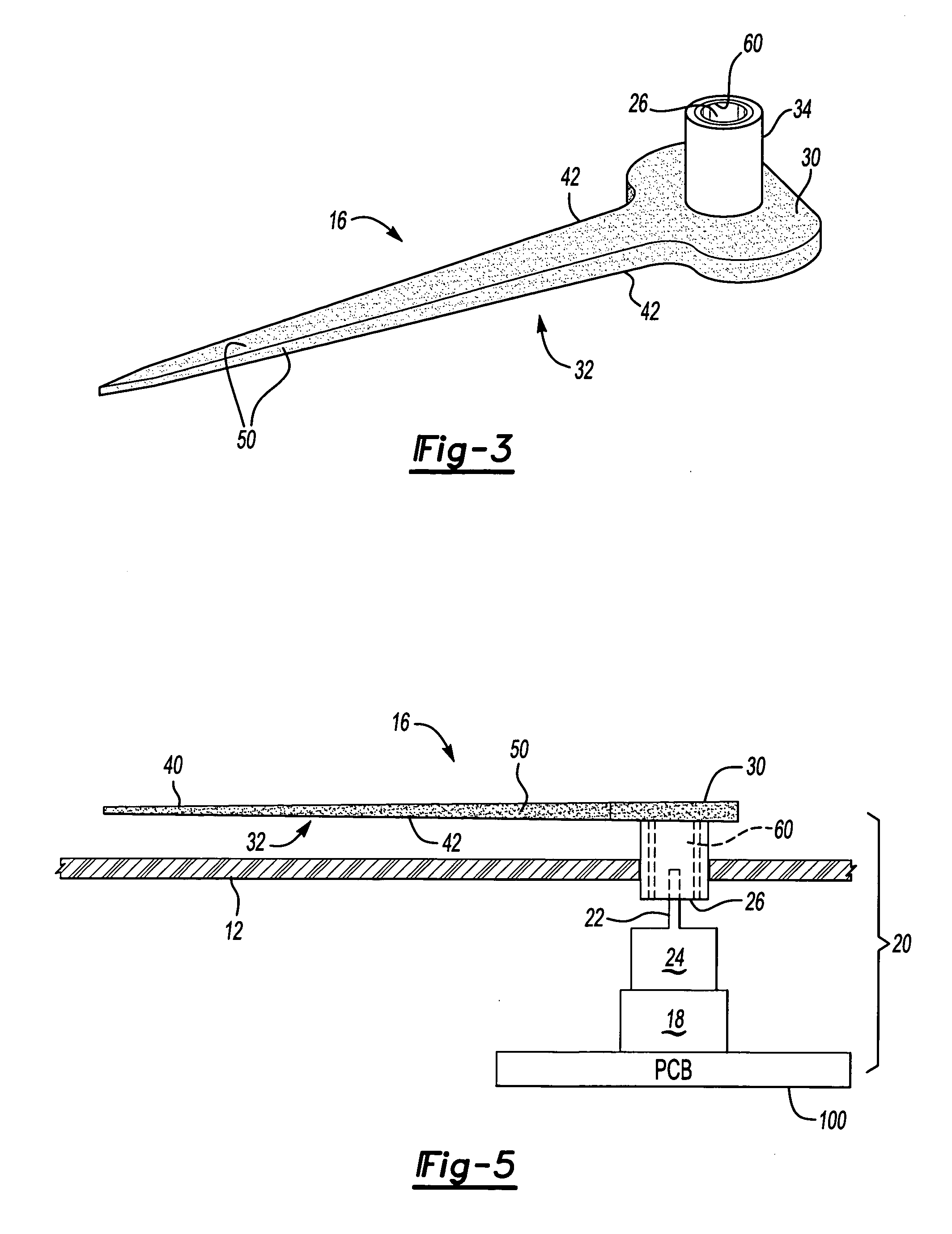
[0018] An example pointer...


PUM


Abstract

An illuminated instrument assembly includes an instrument cluster having a graphical image and a pointer moveable relative to the graphical image to indicate a vehicle operating condition. In one example, the pointer has a body and an arm portion. A light source illuminates at least a portion of the pointer. The arm portion of the pointer is at least partially coated with a surface finish comprising a metal substrate to eliminate light bleed and the halo effect that may occur when viewing the graphical image.

Description

BACKGROUND OF THE INVENTION [0001] This application claims priority to U.S. Provisional Patent Application Ser. No. 60 / 607,401 filed Sep. 3, 2004.[0002] This invention generally relates to an illuminated pointer for an instrument panel, and more particularly to an illuminated pointer that controls light from escaping from an arm portion of the pointer and reflecting onto surrounding surfaces. [0003] A vehicle instrument panel typically includes several gauges for displaying and conveying information to a driver. The instrument panel typically includes a speedometer along with other gauges such as a tachometer, battery level indicator, and oil pressure gauge. Typically a pointer is mounted to move relative to a fixed graphical image on each gauge. [0004] The pointer is typically one of two basic types, either a non-active pointer or an active pointer. A non-active pointer is illuminated by a light source mounted to a circuit board positioned behind a light transparent output shaft. L...

Claims


Application Information

Patent Timeline
IPC IPC(8): G01D11/28
CPCG01D13/265G01D11/28B60K2370/6992
Inventor DYER, KEVIN
Owner SIEMENS VDO AUTOMOTIVE CORP
Why Eureka
Try Eureka