Image encoding apparatus and method, computer program, and computer-readable storage medium

Inactive Publication Date: 2006-03-09
CANON KK
View PDF60 Cites 17 Cited by
  • Summary
  • Abstract
  • Description
  • Claims
  • Application Information

AI Technical Summary

Benefits of technology

[0012] The present invention has been made in consideration of the above situation, and has as its object to provide a technique of efficiently compression-encoding an im

Problems solved by technology

When the JPEG scheme is used in a system which stores data in a limited memory, an overflow of memory may occur.
However, the compression encoding technique in Japanese Patent Laid-Open No. 2003-8903 uses only a lossy compression technique such as JPEG.

Method used


Image

  • Image encoding apparatus and method, computer program, and computer-readable storage medium
  • Image encoding apparatus and method, computer program, and computer-readable storage medium
  • Image encoding apparatus and method, computer program, and computer-readable storage medium

Examples


Example

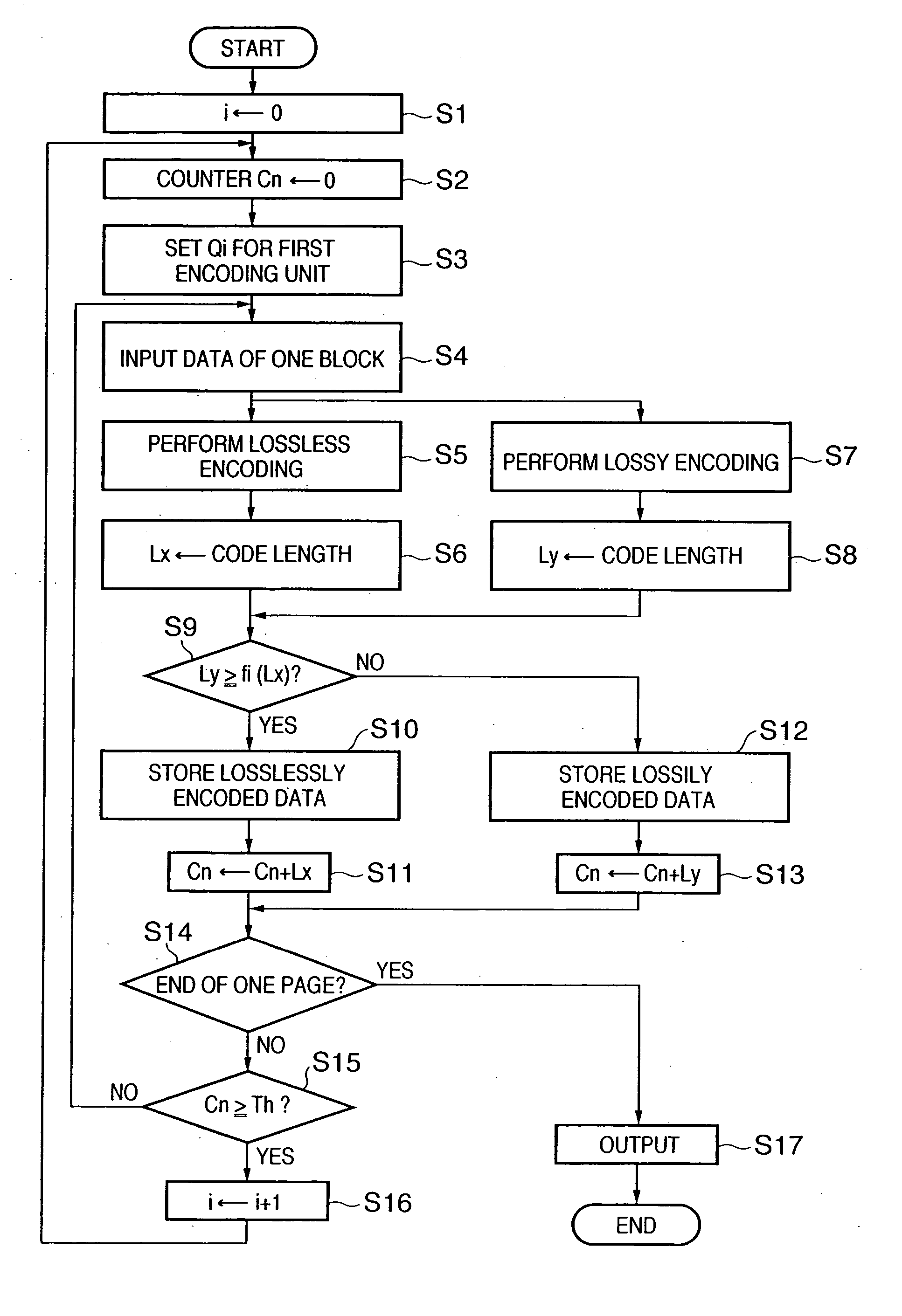
[0106] In the above embodiment (first embodiment), when a generated encoded data amount exceeds a target data amount during encoding of one page, image data is input again.

[0107] The second embodiment will describe an example in which encoded data of a target data amount or less is generated without inputting a 1-page image again.

[0108] The arrangement of an apparatus is the same as that in FIG. 22, and the second embodiment will be explained by giving attention to an encoding unit 6.

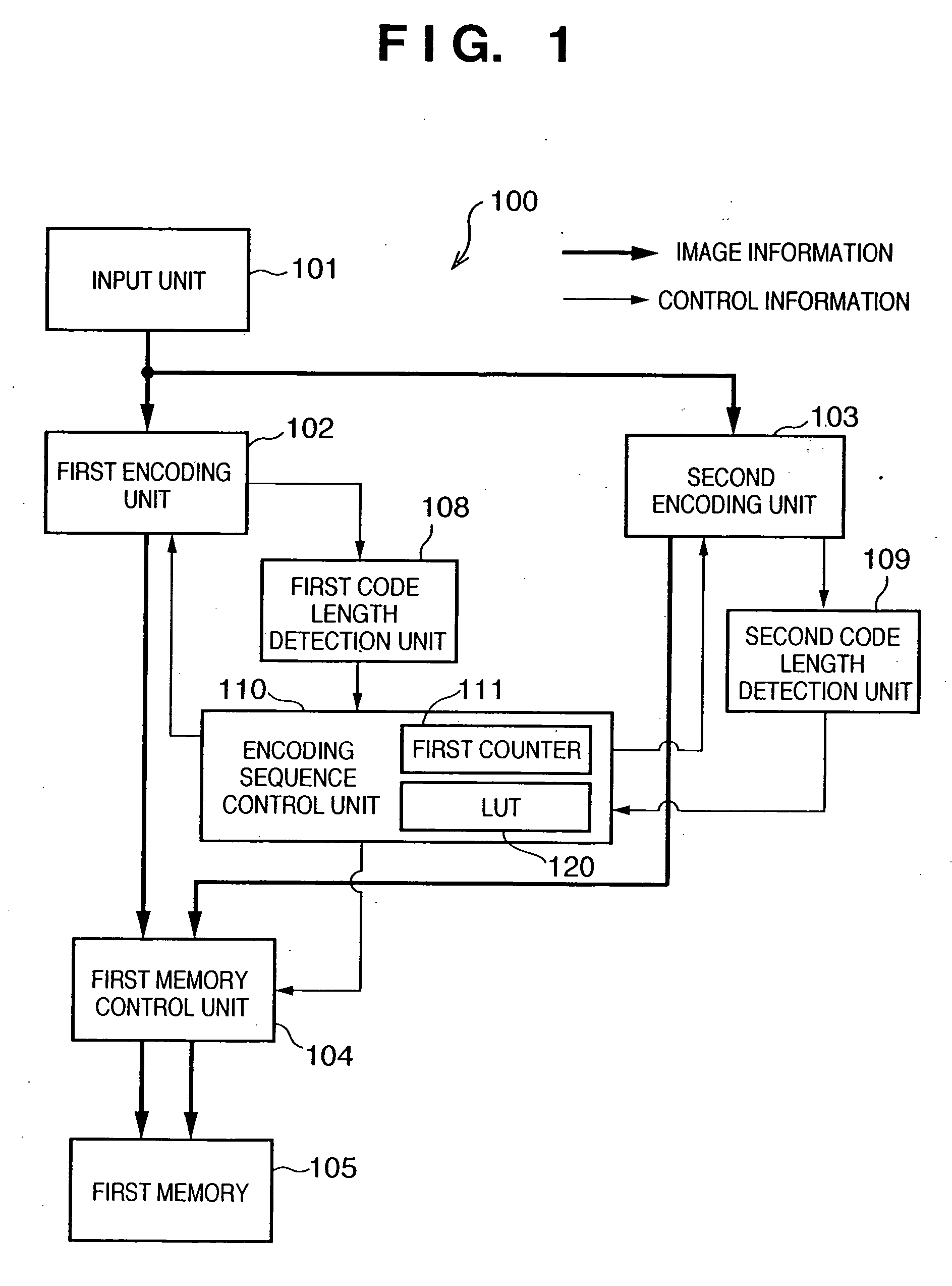
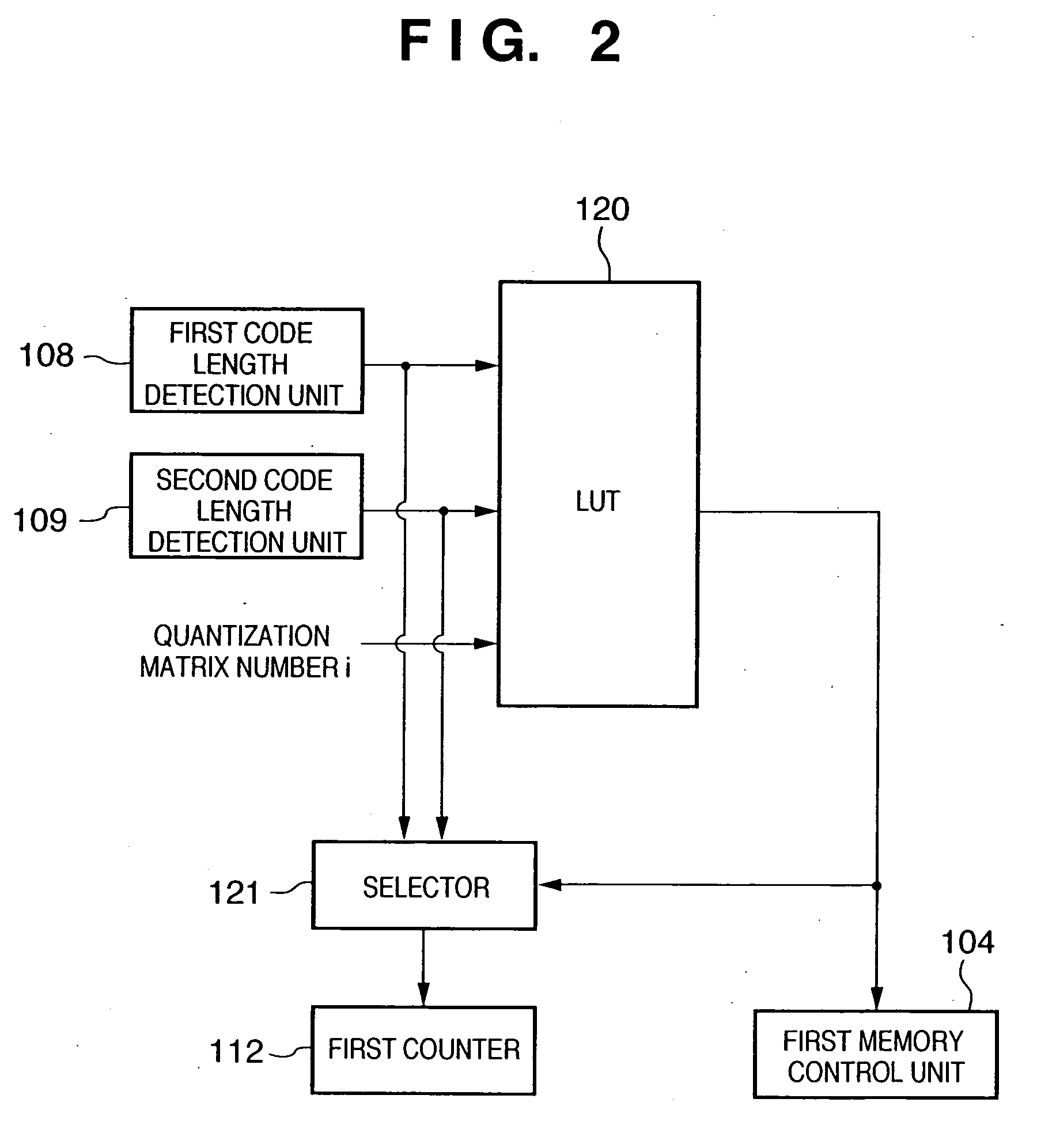
[0109]FIG. 4 is a block diagram showing the encoding unit 6 according to the second embodiment. The encoding unit 6 is different from that in FIG. 1 in that a second memory control unit 106, second memory 107, re-encoding unit 112, and second counter 113 are added. The remaining arrangement is the same as that in FIG. 1, and the same reference numerals denote the same parts.

[0110] A first memory 105 stores encoded data which is selected in accordance with the same determination criterion as that in ...

Example

First Modification to Second Embodiment

[0169]FIG. 14 shows a modification of the arrangement in FIG. 4. The arrangement in FIG. 14 is different from that in FIG. 4 in that the storage destination of data re-encoded by the re-encoding unit 112 is changed to the first memory 105. The remaining arrangement is the same as that in FIG. 4.

[0170]FIG. 15 shows a state in which the total encoded data amount in the first memory 105 exceeds a target data amount, data in the first memory 105 is discarded, and re-encoding of encoded data (area I′ in FIG. 15) stored in the second memory 107 starts.

[0171] As shown in FIG. 15, the first memory 105 is set as the storage destination of re-encoding by the re-encoding unit 112, and re-encoding starts.

[0172]FIG. 16 shows the storage state of encoded data in two memories upon the completion of re-encoding. Upon the completion of re-encoding, as shown in FIG. 16, the first memory 105 stores encoded data represented in the area I. Encoded data in the a...

Example

Second Modification to Second Embodiment

[0177] In the second embodiment and first modification, when the encoded data amount in the first memory 105 exceeds a target data amount, encoded data in the second memory 107 is re-encoded by the re-encoding unit 112. In other words, the re-encoding unit 112 does not execute re-encoding while the encoded data amount in the first memory 105 falls within the target data amount.

[0178] An example of effectively using this period will be explained as the second modification.

[0179] The following description is directed to a process while losslessly encoded data from the second encoding unit 103 is stored in the second memory 107 when the encoded data amount in the first memory 105 falls within the target data amount, under the condition that the quantization matrix table set for the first encoding unit 102 is Qi.

[0180] Similar to the second embodiment, losslessly encoded data from the second encoding unit 103 is stored in the second memory 107...


PUM


Abstract

According to this invention, degradation of the image quality of a decoded image is reduced while losslessly encoded data and lossily encoded data coexist. For this purpose, a first encoding unit performs JPEG encoding for each pixel block, and a second encoding unit performs JPEG-LS encoding. Letting Lx be the code length of encoded data generated by the first encoding unit and Ly be the code length of encoded data generated by the second encoding unit, an encoding sequence control unit selects one of the two encoded data and stores the selected data in a first memory in accordance with whether Lx and Ly satisfy a predetermined non-linear boundary function f( ): Ly≧a f(Lx). At this time, when the axis of abscissas represents the code length of the encoded data generated by the second encoding unit and the axis of ordinates represents that of the encoded data generated by the first encoding unit, the non-linear boundary function f( ) has a curved portion at the two code lengths.

Description

FIELD OF THE INVENTION [0001] The present invention relates to a technique of encoding image data. BACKGROUND OF THE INVENTION [0002] As a conventional still image compression scheme, a JPEG scheme using discrete cosine transformation and a scheme using Wavelet transformation are often adopted. An encoding scheme of these types is a variable-length encoding scheme, and hence the code amount changes for each image to be encoded. [0003] According to the JPEG scheme as an international standardization scheme, only one quantization matrix can be defined for an image, and the code amount cannot be adjusted without a prescan. When the JPEG scheme is used in a system which stores data in a limited memory, an overflow of memory may occur. [0004] In order to prevent this, conventional schemes use, for example, a method of re-reading a document upon changing the compression ratio when the actual code amount exceeds an expected code amount, or a method of estimating a code amount in advance by...

Claims


Application Information

Patent Timeline
IPC IPC(8): G06K9/36
CPCH04N19/176H04N19/172H04N19/15H04N19/60H04N19/436H04N19/124H04N19/152H04N19/192H04N19/423H04N19/12
Inventor TAMURA, HIROKAZUITO, NAOKI
Owner CANON KK
Why Eureka
Try Eureka