Miniature pump for liquid cooling system

a liquid cooling system and miniature pump technology, applied in the field of pumps, can solve the problems of reducing affecting the cooling efficiency of the whole system, so as to eliminate the flow turbulence

Inactive Publication Date: 2006-03-09
HON HAI PRECISION IND CO LTD
View PDF4 Cites 20 Cited by
  • Summary
  • Abstract
  • Description
  • Claims
  • Application Information

AI Technical Summary

Benefits of technology

[0007] The present invention is directed to a miniature pump which can eliminate the flow turbulence therein.

Problems solved by technology

The conventional heat dissipating devices such as combined heat sinks and fans are not competent for dissipating so much heat any more.
A problem existing in the conventional liquid cooling system is that in operation the liquid entering the inner space via the inlet directly strikes the blades, which causes a flow turbulence in the inner space of the pump.
This flow turbulence slows down the circulation of the liquid and therefore lowers the cooling efficiency of the whole system.

Method used


Image

  • Miniature pump for liquid cooling system
  • Miniature pump for liquid cooling system
  • Miniature pump for liquid cooling system

Examples


Embodiment Construction

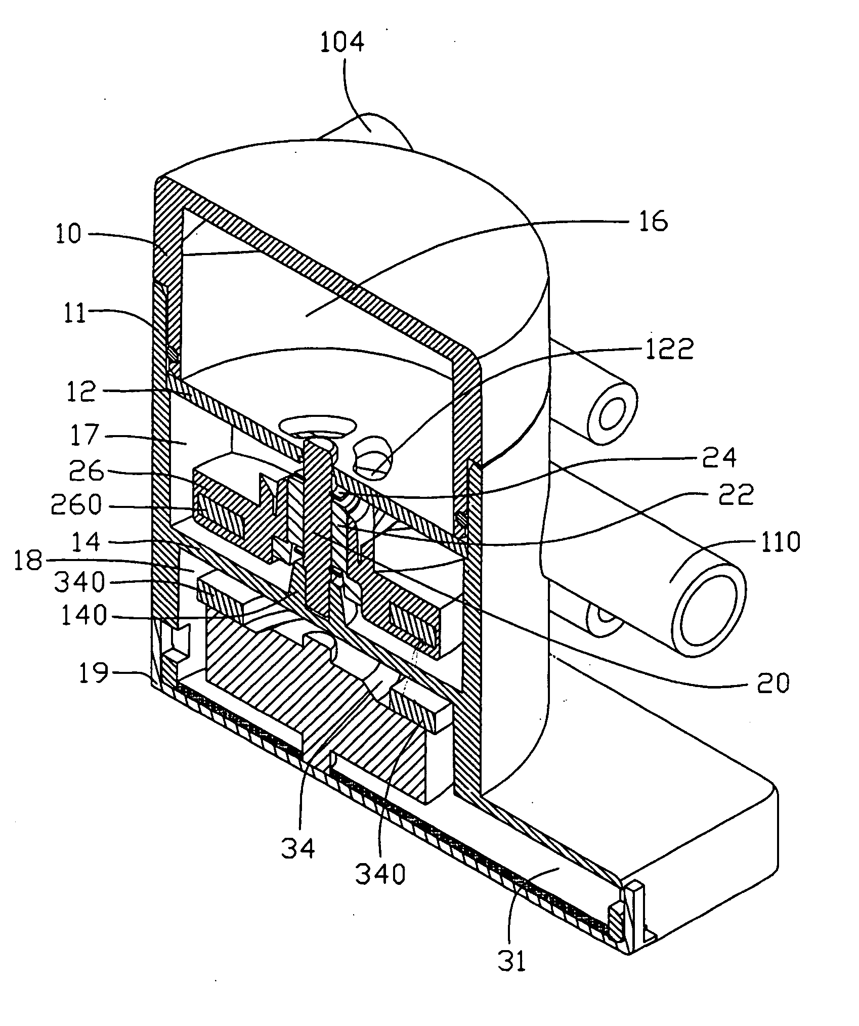
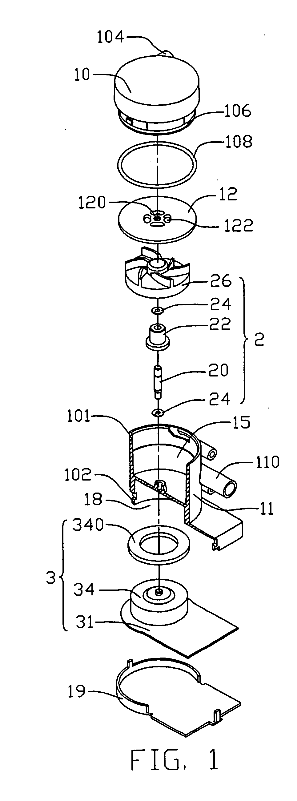
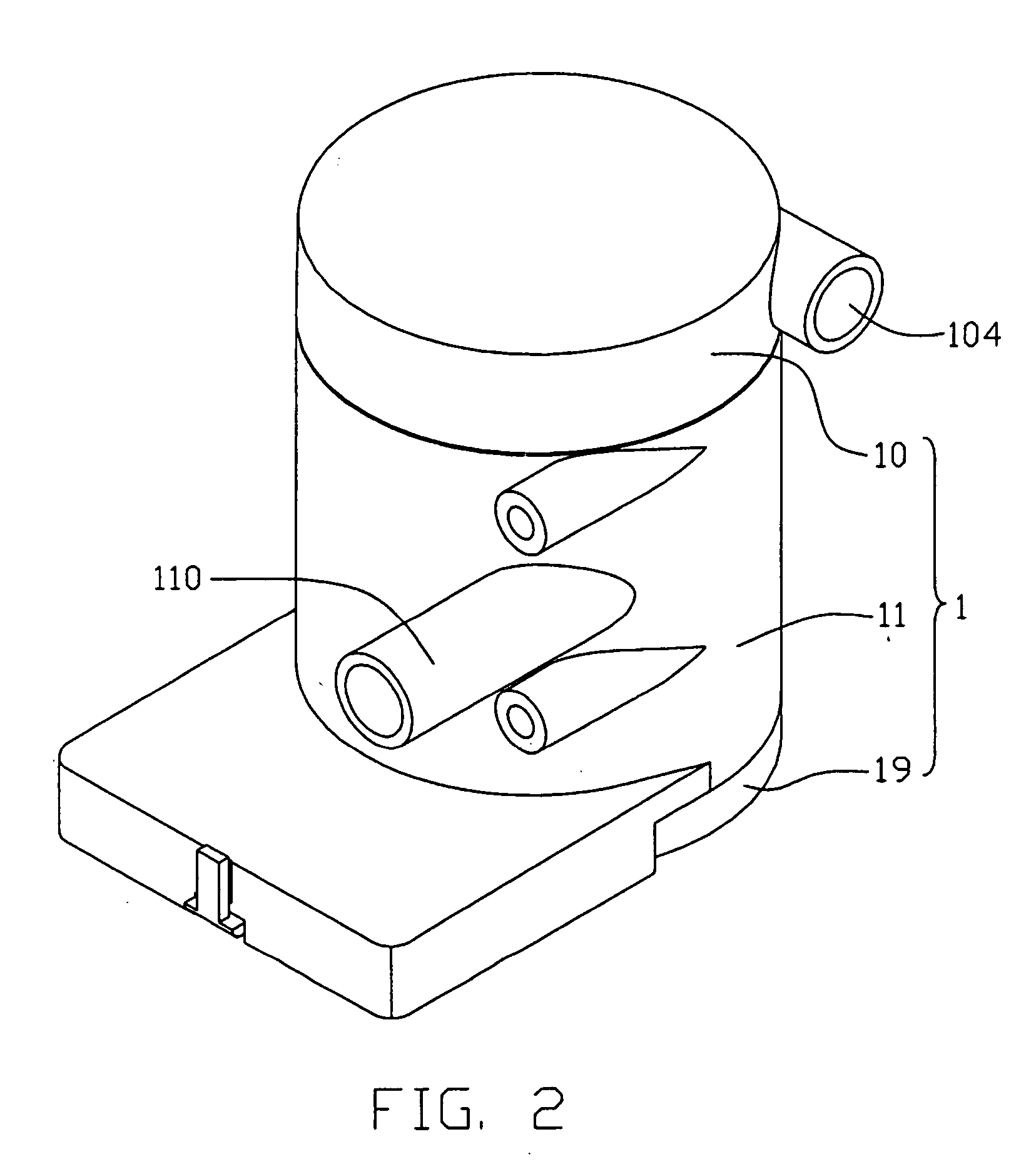
[0014] Referring to FIGS. 1 and 2, a miniature pump in accordance with a preferred embodiment of the present invention comprises a pump casing 1 having an inner space, and a liquid circulating unit 2 and a motor driving unit 3 received in the inner space of the pump casing 1.

[0015] The pump casing 1 comprises a hollow main body 11, a top cover 10 hermetically attached to a top end 101 of the main body 11, and a bottom cover 19 attached to a bottom end 102 of the main body 11. A sealing ring 108 is disposed between the main body 11 and the top cover 10 to prevent liquid leakage. The top cover 10 forms an annular groove 106 at a bottom edge thereof for receiving a sealing ring 108 therein. An inlet 104 is formed on the top cover 10 for allowing liquid to enter the pump casing 1. An outlet 110 is formed on the main body 11 for allowing the liquid to exit the pump casing 1.

[0016] The main body 11 transversely forms an inner partition wall 14. This partition wall 14 effectively divides...


PUM


Abstract

A miniature pump in accordance with the present invention comprises a pump casing (1) and a liquid circulating unit (2) received in the pump casing. The pump casing defines an enclosed space (15) for storing liquid therein. A spacing plate (12) is arranged in the pump casing to divide the enclosed space into a first chamber (16) and a second chamber. The spacing plate defines a through opening (122) at a center portion thereof to make the first and second chambers communicate with each other. An inlet (104) and an outlet (110) are formed on the pump casing respectively communicating with the first and second chambers. The liquid circulating unit is mounted in the second chamber for circulating the liquid in a liquid cooling system.

Description

CROSS-REFERENCE TO RELATED APPLICATIONS [0001] This application is related to a co-pending U.S. patent application entitled “MINIATURE PUMP FOR LIQUID COOLING SYSTEM”, filed Dec. 17, 2004, and assigned Ser. No. 11 / 015,488, with the same assignee as the instant application. The disclosure of the above-identified application is incorporated herein by reference.TECHNICAL FIELD [0002] The present invention relates generally to pumps, and more particularly to a miniature pump for a liquid cooling system for cooling an electronic package. BACKGROUND [0003] With continuing development of the computer technology, electronic packages such as the CPUs are generating more and more heat that is required to be dissipated immediately. The conventional heat dissipating devices such as combined heat sinks and fans are not competent for dissipating so much heat any more. Liquid cooling systems have thus been increasingly used in computer technology to cool these electronic packages. [0004] A typical...

Claims


Application Information

Patent Timeline
Patent Type & Authority Applications(United States)
IPC IPC(8): F04B17/00F04B35/04F04D13/06
CPCF04D13/064F04D13/0666
Inventor LEE, HSIEH-KUNLAI, CHENG-TIENZHOU, ZHI-YONG
Owner HON HAI PRECISION IND CO LTD
Why Eureka
Try Eureka