Microfluidic device for the encapsulation of cells with low and high cell densities

a microfluidic device and cell technology, applied in the field of cell encapsulation, can solve the problems of increasing the size dispersion of small droplets, inability to trap droplets before (or without) polymerization, and non-uniform polymerization times across droplet population, and achieve uniform polymerization times and small minimum droplets.

Active Publication Date: 2006-03-09
RGT UNIV OF CALIFORNIA
View PDF1 Cites 190 Cited by
  • Summary
  • Abstract
  • Description
  • Claims
  • Application Information

AI Technical Summary

Benefits of technology

[0011] The advantages of the apparatus and methods provided herein include much smaller minimum droplet size (˜20 μm or less), mono-dispersity of size, ability to trap the droplets before (or without) polymerization, and uniform polymerization times across droplet population due to continuous (rather than batch) nature of the process.

Problems solved by technology

These methods have their disadvantages including, e.g., a minimum droplet size, an increase in size dispersion for small droplet sizes, an inability to trap the droplets before (or without) polymerization, and non-uniform polymerization times across droplet population.
These methods produce larger droplets.

Method used


Image

  • Microfluidic device for the encapsulation of cells with low and high cell densities
  • Microfluidic device for the encapsulation of cells with low and high cell densities
  • Microfluidic device for the encapsulation of cells with low and high cell densities

Examples


Embodiment Construction

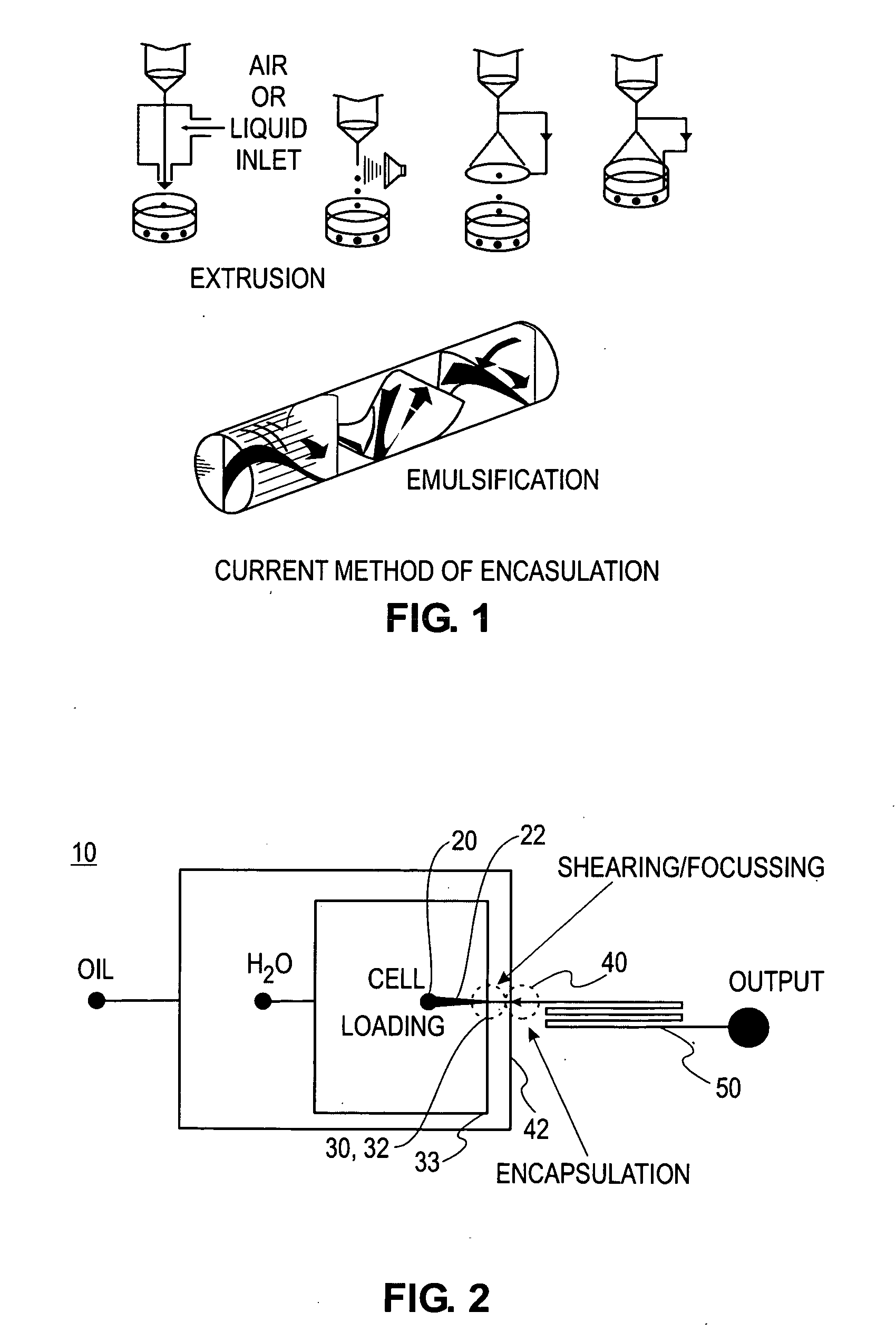
[0041]FIG. 2 is a schematic of an exemplary system for encapsulating cells in droplets. The system 10 generally includes a microfluidic device comprising a series of intersecting channels which form a cell loading region 20, a shearing region 30, a focusing region 32, an encapsulation region 40, and a serpentine output 50. As is described further below, the methods of this embodiment can be combined with further functional regions to, for example, obtain polymerized droplets, sort out empty droplets, or combinatorially add biochemical factors. In addition, methods that do not include one or more of the functional regions can also be employed.

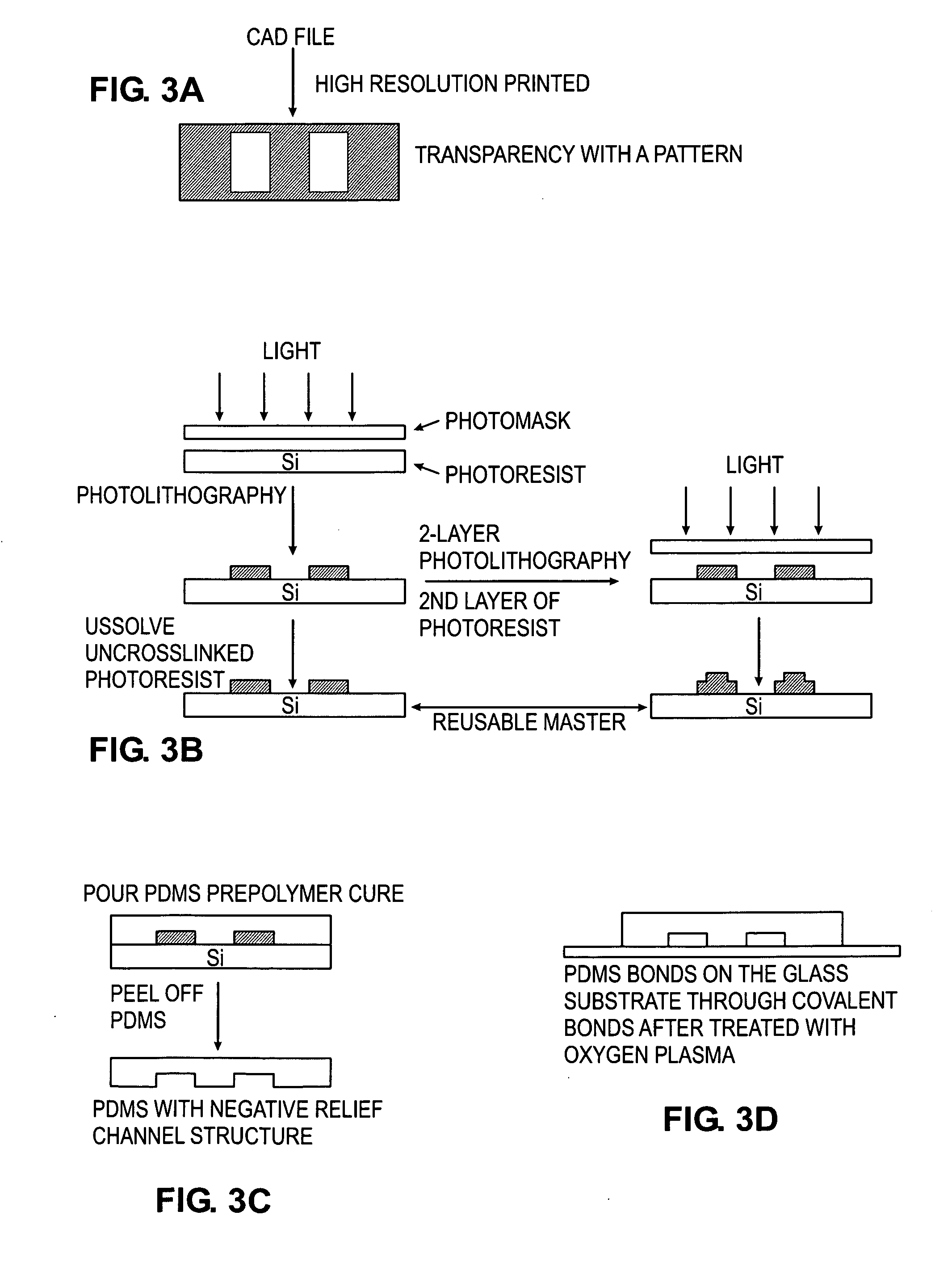
[0042] As depicted in FIG. 3, polydimethylsiloxane (PDMS) is preferably used as a material for fabricating the microfluidic device. The PDMS used is supplied in two components, a base and a curing agent. The mixture is introduced on top of a silicon wafer formed with photosensitive polymer formed lithographically into the desired channel design...


PUM

PropertyMeasurementUnit
diameteraaaaaaaaaa
sizeaaaaaaaaaa
depthaaaaaaaaaa

Abstract

Devices and methods for the encapsulation of cells on microfluidic platforms are disclosed. The microfluidic device generally includes a plurality of functional regions to shear, focus, and encapsulate a desired cell or group of cells into a droplet. The microfluidic device can further comprise a polymerization zone to form a polymer bead around the droplet.

Description

CROSS REFERENCE TO RELATED APPLICATIONS [0001] This application claims the benefit of U.S. provisional application No. 60 / 605,010 filed Aug. 27, 2005, the disclosure of which is hereby incorporated by reference.FIELD OF THE INVENTION [0002] The present invention relates to cell encapsulation and, more particularly, to a microfluidic device for the encapsulation and polymerization of cells with low cell densities in which individual cells are not adhered to one another, and higher cell densities in which the cells form clusters that may be larger than the channel dimensions. BACKGROUND OF THE INVENTION [0003] Bioencapsulation, which has provided a range of promising therapeutic treatments for diabetes, hemophilia, cancer, and renal failure, emerged as a new area for research for biomedical engineering in 1964 with the use of ultrathin polymer membrane microcapsules, or “artificial cells”, for the immunoprotection of transplanted cells. [Chang, Science 146, 524-525 (1964)]. Twenty yea...

Claims


Application Information

Patent Timeline
Patent Type & Authority Applications(United States)
IPC IPC(8): C12N15/00
CPCB01F3/0807B01F5/0646C12N11/04B01F13/0062B01F5/0647B01F23/41B01F25/4331B01F25/433B01F33/3011
Inventor LEE, ABRAHAM PHILLIPFISHER, JEFFREY S.
Owner RGT UNIV OF CALIFORNIA
Why Eureka
Try Eureka