System and method for controlling a design process

a technology of design process and system, applied in the field of system and method for controlling a design process, can solve the problems of limited intelligent and timely interaction between related design sub-processes, small guarantee, and often far from optimum design process

Inactive Publication Date: 2006-03-09
ORORA PACKAGING AUSTRALIA
View PDF17 Cites 10 Cited by
  • Summary
  • Abstract
  • Description
  • Claims
  • Application Information

AI Technical Summary

Benefits of technology

[0023] In these embodiments, the system typically allows the constraints to be defined as “hard” constraints which cannot be breached or “soft” constraints which can be breached if other conditions are satisfied.
[0024] In one embodiment, the system further comprises an optimisation engine for optimising the design process using one or more rules to analyse available solutions of the design process.

Problems solved by technology

As a result, there is limited intelligent and timely interaction between related design sub-processes as well as little to ensure that the outcomes of individual design sub-processes are consistent with the goals of the design process and satisfy some local and / or global optimum requirement.
Accordingly, the outcome of the design process is often far from optimum and the design process itself can follow a convoluted path requiring many iterations.
As a result, the design process typically takes much longer and requires much more effort than is desirable.
Further, existing systems make it difficult for different entities to engage within an integrated design space.

Method used


Image

  • System and method for controlling a design process
  • System and method for controlling a design process
  • System and method for controlling a design process

Examples


example 1

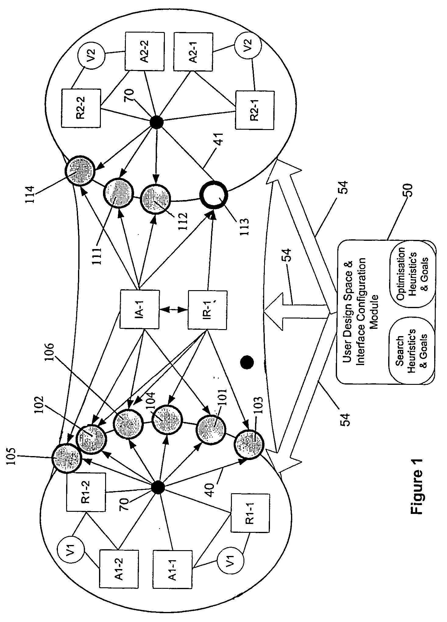
[0054] In order to facilitate understanding of the invention, an example of an embodiment involving two sub-processes will be described where the first sub-process (SP1) is a carton and the second sub-process (SP2) is a corrugated box. FIG. 1 provides a schematic representation of the components in the system, eg variables, algorithms and rules. FIG. 1 shows the connection between variables, algorithms, and rules and the passive and active interface variables. In this example all algorithms and rules may modify or examine an interface variable. Accordingly, in FIG. 1, all lines are shown passing through a central hub 70 to indicate that all rules / algorithms may communicate with all variables. The directed lines (i.e. lines with arrows, e.g. line 40) show where a sub-process algorithm or rule may change an active variable. As shown within sub-process 2 where a passive variable cannot be changed by the algorithms and rules of the sub-process, non-directed lines (i.e. lines without arr...

example 2

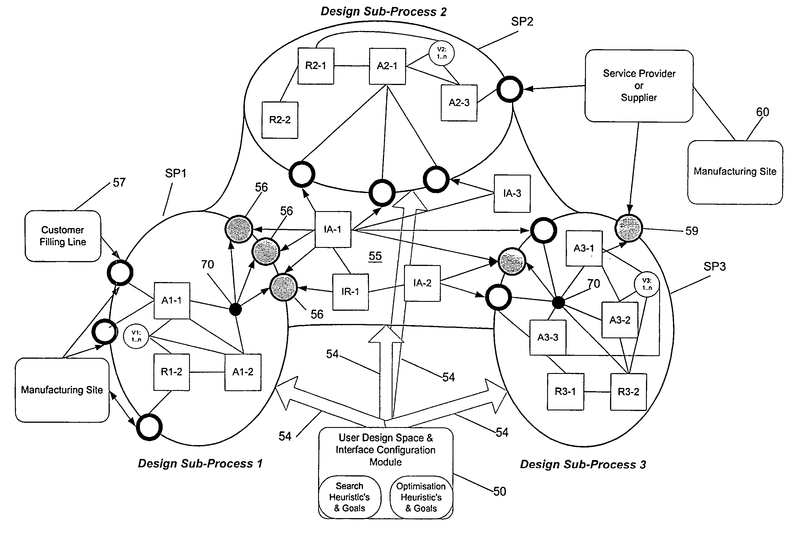
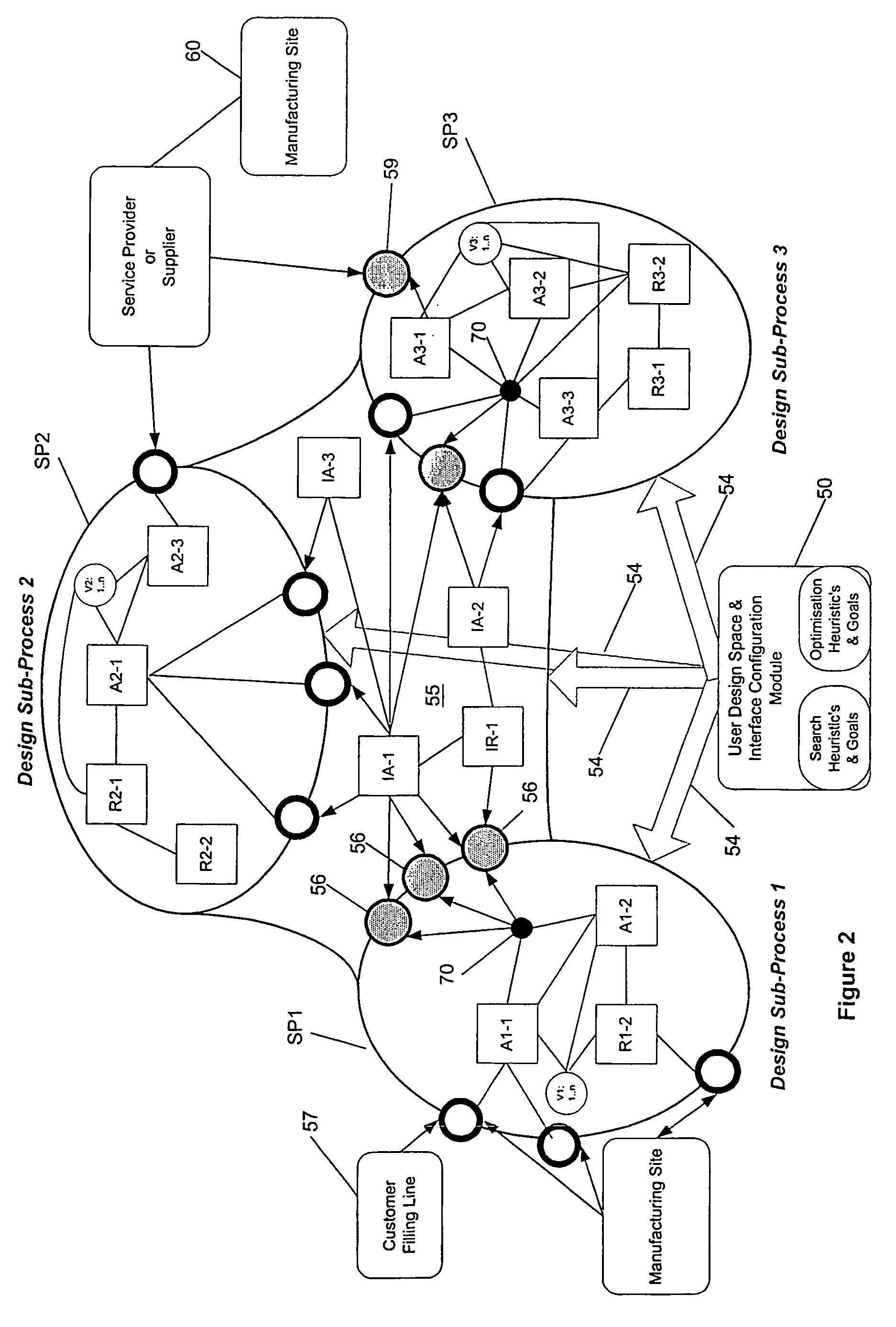
[0088] Referring now to FIG. 2 there is shown a schematic representation of an interface between three sub-processes. The second example is for illustrative purposes of potential functions and does not relate to specific sub-processes. Box 50 indicates the user interface configuration module which is used by the project manager to configure the design process as indicated by arrows 54. In this embodiment the project manager is capable of configuring first design sub-process SP1, second design sub-process SP2 and third design sub-process SP3 as well as configuring interface 55.

[0089] As shown by design sub-process 1, a design sub-process may incorporate a number of different algorithms which interact with the variable set under the control or management of a rules engine R1-1. The set of variables 56 are all active and hence tend to drive the overall design process. However, the algorithms A1-1 and A1-2 also interact with other passive variables related by filling line 57 and manufa...


PUM


Abstract

A system for controlling a design process having a first design sub-process (SP1) and a second design sub-process (SP2), outcomes of one of the first and second design sub-processes (SP1, SP2) being linked to outcomes of the other of the design sub-processes by a relationship between one or more first design sub-process variables (A) and one or more second design sub-process variables (B). The system comprises a user configurable interface (I) between the first and second design sub-processes (SP1, SP2), the interface allowing a user to the system to control the design process by specifying which of the one or more variables (A, B) (101-106, 111-114) are active variables which can have their domains modified by at least internal process within the sub-process to which the variable belongs and which of the one or more variables (A, B) are passive variables which have their domains determined within allowable values by the domains of the other variable(s) in the relationship.

Description

[0001] The present invention relates to a system for controlling a design process which finds particular application in the packaging industry. FIELD OF THE INVENTION [0002] In many industries the design process consists of a number of sub-design processes which relate to the overall design of a product or process. These individual design sub-processes must be combined to produce an integrated outcome. For example, in the packaging industry in order to deliver a product to consumers there needs to be a single consistent outcome including the flexible wrap which surrounds the product, the carton in which the flexibly wrapped products are contained for presentation at retail stores and the corrugated box in which the individual cartons are shipped to the retailer. The individual elements are the result of a number of individual design sub-processes which need to be combined and consistent overall outcome. [0003] Previous approaches to integrating design sub-processes have generally be...

Claims


Application Information

Patent Timeline
Patent Type & Authority Applications(United States)
IPC IPC(8): G06F7/00G06F17/50
CPCG06F17/50G06F2217/38G06F2217/06G06F2111/04G06F2113/20G06F30/00
Inventor SELWAY, JAMES WALKER
Owner ORORA PACKAGING AUSTRALIA
Why Eureka
Try Eureka