
Direct drive windshield wiper assembly

a windshield wiper and assembly technology, applied in the direction of magnetic circuit rotating parts, vehicle cleaning, vehicle shape/form/construction, etc., can solve the problems of excessive wiper movement, large and a large amount of underhood space for mechanical linkag

Inactive Publication Date: 2006-03-16
TRICO PROD CORP
View PDF43 Cites 52 Cited by
  • Summary
  • Abstract
  • Description
  • Claims
  • Application Information

AI Technical Summary

Benefits of technology

[0021] Another advantage of the present invention is that it employs a position sensor that senses the rotational speed and position of the windshield wiper and will not loose its position parameter even in the event of a power loss. Thus, the windshield wiper system of the present invention will not become unsynchronized and therefore will not clash due to an inability to maintain the sense of wiper arm position.
[0022] Another advantage of the present invention is that it employs a latching mechanism that secures the motor and thus the output of the motor in a non-rotational disposition when the motor is off.
[0023] Another advantage of the present invention is that it includes an integrated control circuitry that achieves position sensing such that the wiper arm position is known regardless of rotation and such that the detected arm position is not lost during power loss or loss of motion.
[0024] Still another advantage of the windshield wiper system of the present invention is that it may be employed in either a standard 12 volt or the more efficient 42 volt-based automotive electrical system.

Problems solved by technology

This approach requires a fairly complex linkage system to convert the singular angular motion of the wiper motor into the two-way linear reciprocal motion to drive both wiper arms.
In the dashboard-firewall area, where these systems are typically installed, this mechanical linkage requires a large amount of underhood space.
Additionally, the moving linkage, with its several pivot and rotational points is subject to mechanical inaccuracies and wear, readily introducing excessive wiper movement.
Nevertheless, for many years, designers and manufacturers were reluctant to depart from this established approach.
However, improved vehicle aerodynamics that have fostered vehicle designs having longer sloped front surfaces are leading to windshield designs with more pronounced rake angles that result in larger window surfaces.
This has created a number of problems.
Most notably, the larger arms and swept surface area increases the size of conventional wiper systems to such an extent that it becomes difficult to fit a single motor system within the typically allotted underhood space.
This problem is further aggravated by the same aerodynamic sloped front surfaces of the newer vehicle designs, which reduce the available underhood space.
This undesirably requires separate motor control circuitry and a reliance on the movement of the wiper motors to provide positional feedback.
While suitable for use in windshield wiper systems, the use of the above-noted brushless dc motor controllers in a windshield wiper system that uses separate position sensors for coordination of the wipers can result in an unnecessarily complicated design.
Also, any loss of power to the system will disorient and confuse these sensors such that the wiper arm position becomes an unknown.
Thus, windshield wiper systems that employ pulse train type sensors suffer from the disadvantage that they easily loose the accurate position of the windshield wiper blade during common operating conditions and therefore suffer a loss of control in these circumstances.
The build-up of snow and ice on the windshield complicates the control of blade movement and the ability to accurately determine wiper arm position and can impede the movement of the blades unevenly, causing one blade to move faster than the other.
When encountering this problem, electronically controlled wiper systems presently known in the art can often become unsynchronized and may clash as they become unable to maintain their sense of wiper arm position.
This is undesirable, as it requires large counter-rotational forces to stop and then reverse the wiper arm at the end of its sweep.
Also, large current draws are necessary to produce the counter-rotational forces which causes repetitive surges in the supplied power and induces great amounts of electro-magnetic interference to the immediately surrounding parts of the vehicle.
With a high-speed dc motor, it is also problematic to vary the speed of the wiper arm as it sweeps across the windshield, if this is desired as part of a sweeping pattern or predetermined clearing scheme.
These drawbacks stem from the conventional construction of direct drive wiper motors, which have either a one-to-one direct drive or an inefficient gearing assembly to differ the wiper arm speed from motor speed.
One other drawback to conventional wiper motor systems has recently emerged.
The change over to a 42 volt automotive electrical systems will be highly problematic for the prior dual direct drive wiper systems and presents a considerable drawback as the prior systems are not compatible.

Method used


Image

  • Direct drive windshield wiper assembly
  • Direct drive windshield wiper assembly
  • Direct drive windshield wiper assembly

Examples


Embodiment Construction

)

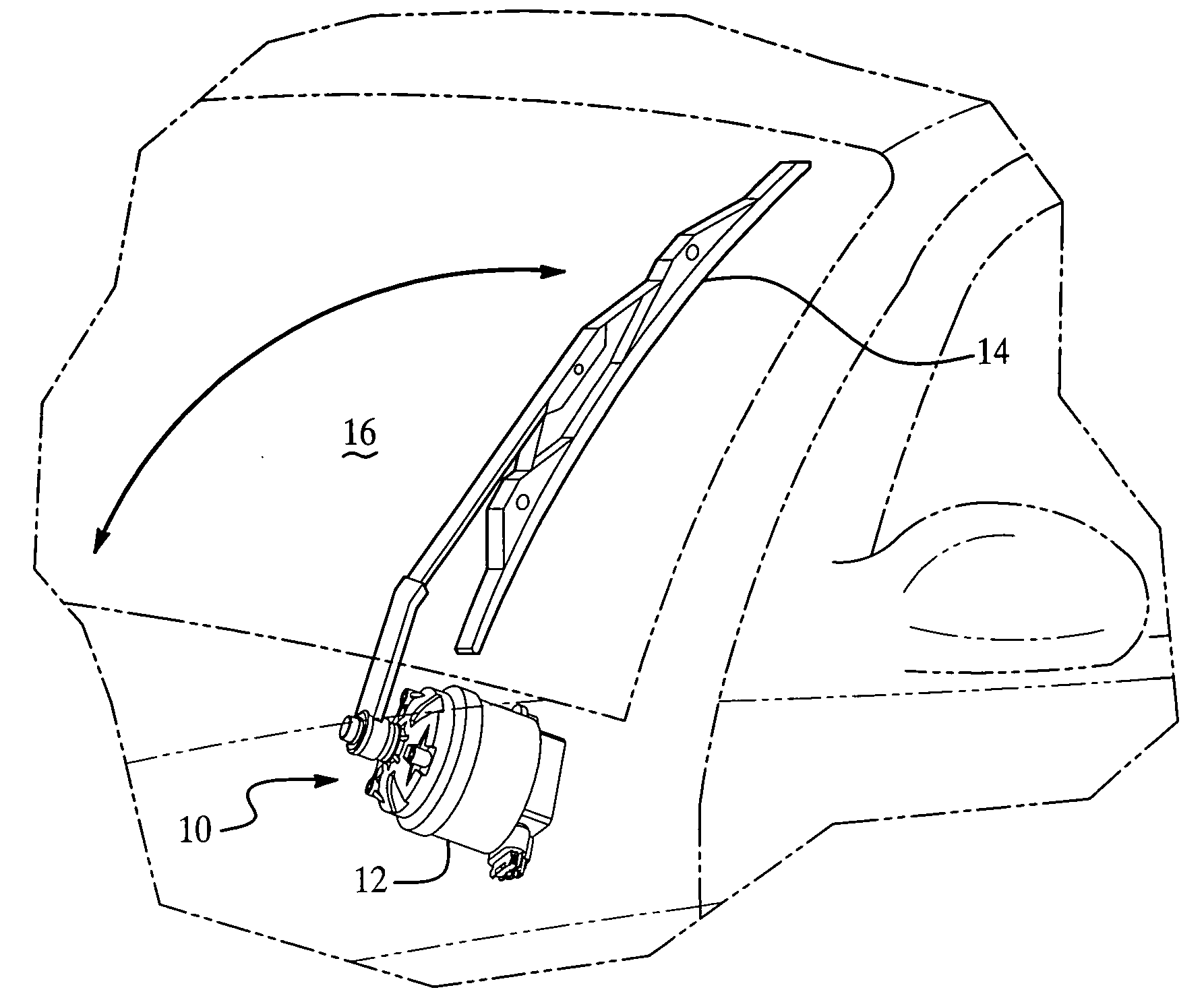
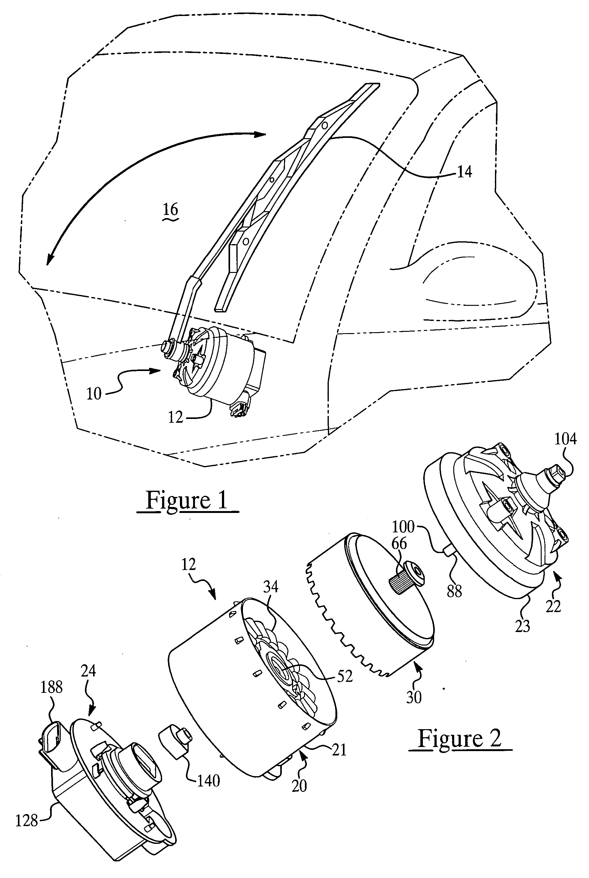
[0039] Referring now to the figures where like numerals are used to designate like structure throughout the drawings, a direct drive windshield wiper assembly of the present invention is generally indicated at 10. As shown in FIG. 1, the direct drive windshield wiper assembly 10 includes at least one motor 12 that rotatably drives a windshield wiper 14 across the surface of a windshield 16. Generally speaking, the motor 12 provides a drive torque through an output that is rotatable about the longitudinal axis of the motor 12 so that the windshield wiper 14 is driven about the same longitudinal axis in a repeated wiping motion across the surface of the windshield 16. The motor 12 further controllable to rotate in either direction, thereby providing bi-directional rotation to the windshield wiper 14. In addition, from the description that follows, those having ordinary skill in the art will appreciate that the windshield wiper assembly of the present invention may encompass two or mo...


PUM


Abstract

A windshield wiper assembly including at least one motor having an output shaft and a windshield wiper operatively connected to the output shaft. The motor includes a stator adapted to provide an electromagnetic flux and a rotor assembly supported for rotation about the stator. The rotor assembly includes a back iron that defines an inner circumference and a plurality of magnets disposed in spaced parallel relationship relative to one another about the inner circumference of the back iron and in radially spaced relationship about the stator. The rotor assembly is operatively connected to the output shaft and responsive to electromagnetic flux generated by the stator so as to provide a rotational force to the output shaft to drive the windshield wiper in repeated wiping motion across the windshield.

Description

CROSS-REFERENCE TO RELATED APPLICATION(S) [0001] The present application is a continuation-in-part of U.S. Ser. No. 10 / 146,190, filed May 15, 2002, entitled “Direct Drive Windshield Wiper Assembly,” issued on Sep. 20, 2005 having U.S. Pat. No. 6,944,906.BACKGROUND OF THE INVENTION [0002] 1. Field of the Invention [0003] The present invention relates generally to windshield wiper systems and, more particularly, to a windshield wiper system that utilizes individual direct drive motors for coordinated, but mechanically independent, control of the windshield wipers. [0004] 2. Description of the Related Art [0005] Windshield wiper systems commonly employed in the related art include pivotally mounted wiper blades that are oscillated across a windshield between an in-wipe position, typically located near the cowl of an automotive vehicle, and an out-wipe position, usually associated with an A-pillar on the vehicle, in the case of the driver side wiper blade in this representative example....

Claims


Application Information

Patent Timeline
Patent Type & Authority Applications(United States)
IPC IPC(8): B60S1/08B60S1/06H02K7/00B60S1/16H02K5/22H02K7/102H02K7/116H02K11/00H02K11/04H02K29/00
CPCB60S1/08B60S1/0814B60S1/166H02K5/10H02K5/225H02K2205/09H02K7/116H02K11/0021H02K11/0073H02K21/22H02K29/00H02K7/1023H02K11/215H02K11/33B60S1/06H02K7/00
Inventor MOEIN, ARMANPECK, DAVID EMERY
Owner TRICO PROD CORP
Features
  • Generate Ideas
  • Intellectual Property
  • Life Sciences
  • Materials
  • Tech Scout
  • Unparalleled Data Quality
  • Higher Quality Content
  • 60% Fewer Hallucinations
Learn More