
Apparatus for vacuum packages and method of controlling it

Inactive Publication Date: 2006-03-16
ZEROPACK +1
View PDF11 Cites 15 Cited by
  • Summary
  • Abstract
  • Description
  • Claims
  • Application Information

AI Technical Summary

Benefits of technology

[0005] Accordingly, the present invention has been made to solve the above-described problems, and it is an object of the present invention to provide an apparatus for vacuum sealing a plastic bag and / or a container and a method of controlling the apparatus, wherein a plastic bag mode is set by pressing a first switch and a second switch together under the control of a digital control unit, such that the plastic bag is automatically sealed in a vacuum state, and a container mode is set by pressing only the second switch under the control of the digital control unit, such that the container is automatically sealed in the vacuum state, which makes it convenient and safe to use.
[0008] It is still another object of the present invention to provide an apparatus for vacuum sealing a plastic bag and / or a container and a method of controlling the apparatus, wherein a vacuum pump and a heater are operated together for a predetermined length of time in a plastic bag mode, thereby greatly improving a degree of vacuum.
[0009] It is yet still another object of the present invention to provide an apparatus for vacuum sealing a plastic bag and / or a container and a method of controlling the apparatus, wherein a vacuum chamber does not need to be vacuumed in a container mode, while solving the leakage of air in the conventional vacuum sealing apparatus.
[0010] It is yet another object of the present invention to provide an apparatus for vacuum sealing a plastic bag and / or a container and a method of controlling the apparatus, wherein vacuum sealing is carried out by simply touching a switch, removing an inconvenience that a vacuum releasing valve or a second switch should be kept to be pressed during the vacuum sealing.
[0012] According to the present invention, the first switch and the second switch are all operated as the upper casing is descended above the lower casing, such that the apparatus becomes in the plastic bag mode under the control of the digital control unit, and the plastic bag is automatically vacuumed by simply touching the switches. Also, according to the present invention, a hose is connected to a suction inlet in the vacuum chamber, such that the vacuum chamber does not need to be vacuumed in a container mode, which enables a leakage problem suffered in the conventional apparatuses to be clearly solved. Furthermore, the installation of the digital control unit and the vacuum releasing valve that stays closed in a normal state completely removes the inconvenience that the vacuum releasing valve or the second switch should be kept to be pressed during the vacuum sealing.

Problems solved by technology

In this case, however, the articles stay good for a predetermined length of time, but as time is elapsed, they get oxidized and decayed by the air charged in the interior of the packaged container or vinyl bag.
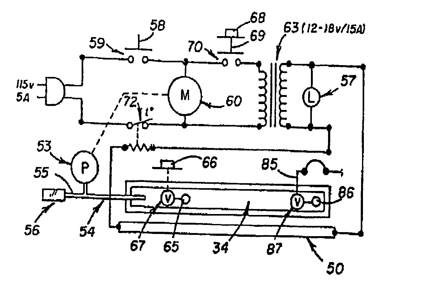
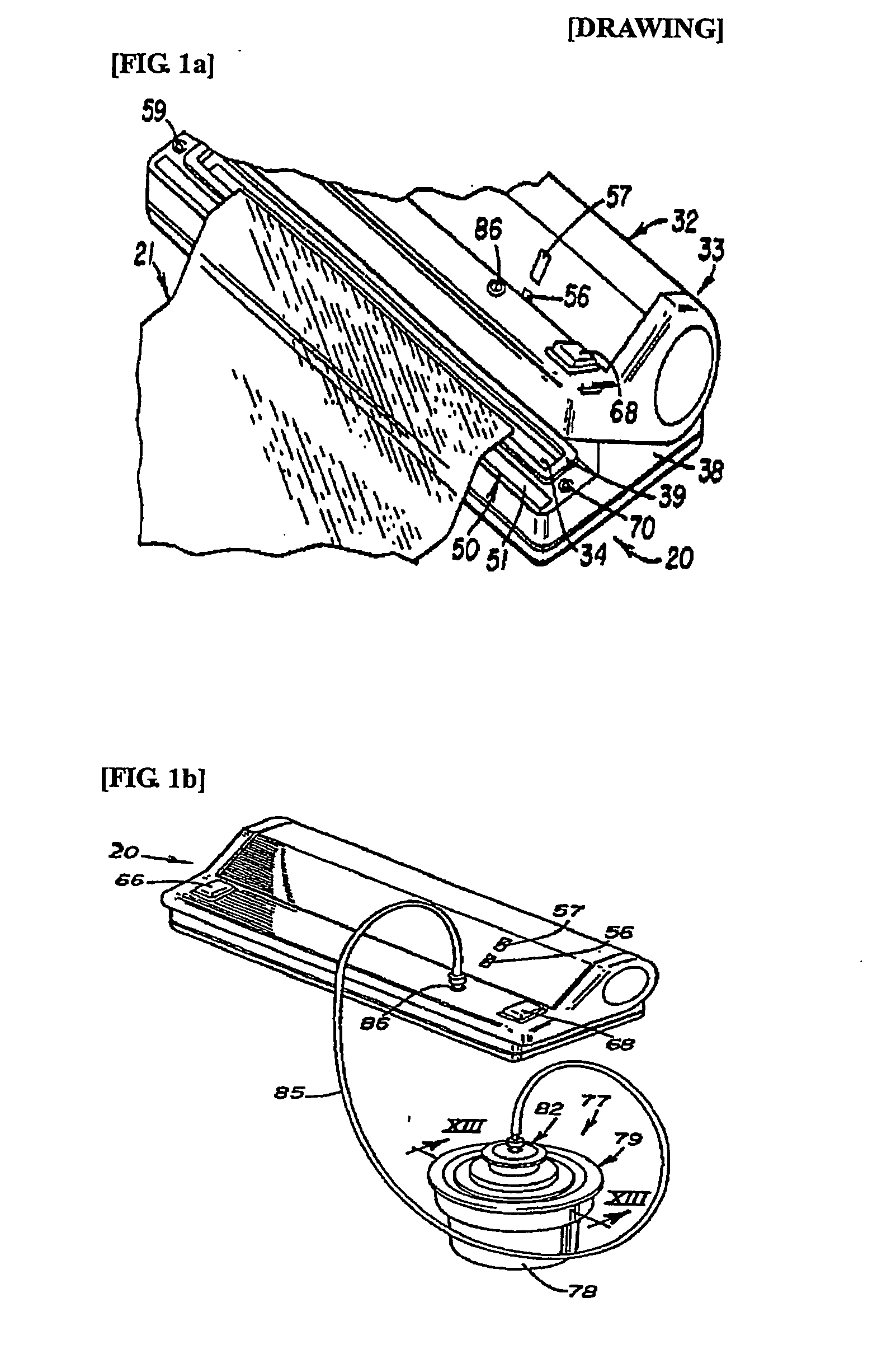
At that time, there occurs a problem that ventilating means 67 (see FIG. 1c) that is opened normally should be continuous to be pressed by means of a button 66 (see FIGS. 1b and 1c) through the user during vacuum sealing, thereby making it inconvenient to use.
This even may make the user get shocked.
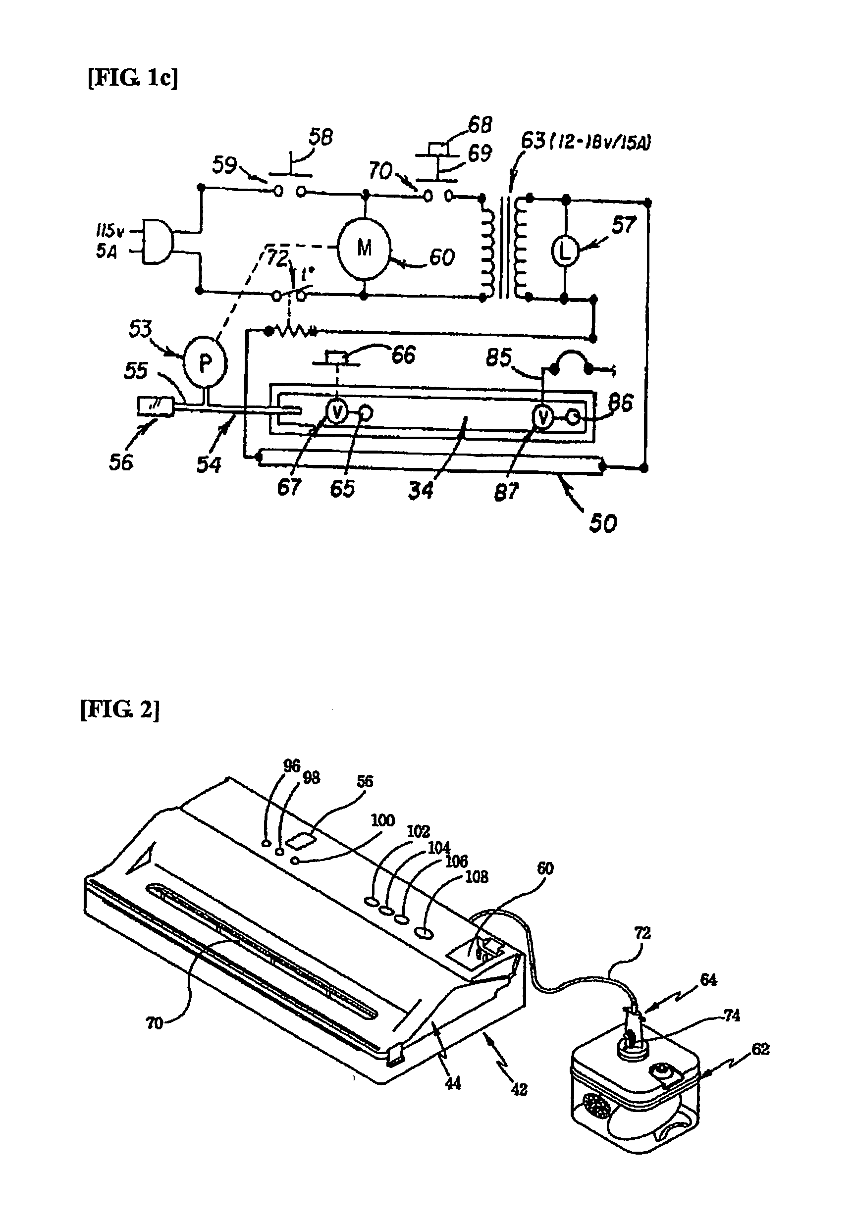
However, there are some inconveniences that the mode should be set by the user and the switch 108 should be also manipulated by the user.
Moreover, vacuum container suction means 64 is connected to a vacuum transferring groove 60 that is placed between the vacuum pump and the vacuum chamber, such that if the vacuum container suction means 64 is not fit well in the vacuum transferring groove 60, the air in the passage from the vacuum chamber to the vacuum pump may be leaked, which causes the vacuum to be incompletely carried out.

Method used


Image

  • Apparatus for vacuum packages and method of controlling it
  • Apparatus for vacuum packages and method of controlling it
  • Apparatus for vacuum packages and method of controlling it

Examples


Embodiment Construction

[0027] Now, an explanation of the preferred embodiments of the present invention will be in detail given with reference to attached drawings. FIGS. 3a to 8b show the preferred embodiments of a vacuum sealing apparatus 100 and a method according to the present invention. First of all, an explanation of the vacuum sealing apparatus 100 will be in detail given.

[0028] As shown in FIGS. 3a and 4, the vacuum sealing apparatus 100 includes an upper casing 200, a lower casing 300, a vacuum chamber 400, a vacuum pump 500, a heater 600, a hose assembly 700 and a digital control unit 800. Thereby, a plastic bag or a container 901 is vacuumed by means of the vacuum sealing apparatus 100. In some cases, the vacuum sealing apparatus can be manufactured only for the purpose of the plastic bag, and desirably, the vacuum pump 500, the heater 600 and the digital control unit 800 are housed in the lower casing 300. The upper casing 200 is pivoted by the lower casing 300 in such a manner as to be open...


PUM


Abstract

Disclosed is an apparatus for vacuum sealing a plastic bag and / or container and a method of controlling the apparatus. The method of controlling the apparatus having an upper casing with an upper concave part therein, a lower casing with a lower concave part therein, a vacuum chamber formed by the close contact between the upper concave part and the lower concave part, such that an opening portion at one end of the plastic bag is inserted into the vacuum chamber, a vacuum pump for providing vacuum to the vacuum chamber, and a heater for heat sealing the plastic bag being in a vacuum sate at the front portion thereof, including the steps of: descending the upper casing above the lower casing to thereby operate a first switch and a second switch together, the first switch and the second switch disposed protrudedly on the contact surface between the upper casing and the lower casing, being connected to a digital control unit; and operating the vacuum pump and the heater in a sequential order by the control of the digital control unit, such that the plastic bag is vacuumed in a plastic mode.

Description

TECHNICAL FIELD [0001] The present invention relates to an apparatus for vacuum sealing a plastic bag and / or a container in which articles like food for storage are put in a vacuum state to thereby prevent the oxidization or decay of the articles and a method of controlling the apparatus, and more particularly, to an apparatus for vacuum sealing a plastic bag and / or a container wherein one of a plastic bag mode and a container mode is selected by just touching switches under the control of a digital control part, such that if the container mode is selected, only the container is vacuumed by connecting a hose to a suction inlet in a vacuum chamber, while the vacuum chamber is not being vacuumed, thereby preventing the air leakage in conventional vacuum sealing apparatuses. BACKGROUND ART [0002] Generally, articles like food for storage are packaged by plastic wrap or a vinyl bag and then placed in refrigerators. In this case, however, the articles stay good for a predetermined length...

Claims


Application Information

Patent Timeline
IPC IPC(8): B65B31/00B65B31/02B65B51/14
CPCB65B31/046B65B51/148B65B51/146B65B31/02
Inventor AHN, JOUNG-GEUNSUNG, EI-JAE
Owner ZEROPACK
Learn More