Gearshift device and method of controlling same

a gearshift and transmission device technology, applied in the direction of mechanical control devices, manual control with single controlling member, instruments, etc., can solve the problems of depriving the driver of a clue, most serious, and the driver is obliged to take his/her eyes off, so as to facilitate the operation of gearshift and increase the effect of recognition

Inactive Publication Date: 2006-03-16
HONDA MOTOR CO LTD
View PDF7 Cites 41 Cited by
  • Summary
  • Abstract
  • Description
  • Claims
  • Application Information

AI Technical Summary

Benefits of technology

[0011] In the above gearshift device, the plurality of shift positions may include a reverse position corresponding to a reverse range and a low position corresponding to a low range, and at least one of the reverse position and the low position may be configured as the retention position. In this exemplary embodiment, the driver may easily recognize the current gear range as being the reverse range or the low range from the sensory feeling of his / her hand. Accordingly, the driver can make a quick and timely decision as to the manipulation of the shift lever during parallel parking of the vehicle or driving through the hills.
[0012] In the above gearshift device, alternatively, the plurality of shift positions may include a neutral position corresponding to a neutral range, a drive position corresponding to a drive range, a reverse position corresponding to a reverse range and a low position corresponding to a low range, whereas the neutral position and the drive position are each configured as the momentary position, and the reverse position and the low position are each configured as the retention position. In this embodiment, the neutral position and the drive position are located on a straight path of the shift lever on which the home position is located between the neutral position and the drive position, and the reverse position and the low position are located off the straight path. According to this exemplary embodiment, the gearshift operation for shifting between the most frequently used neutral and drive positions can be carried out straightforward, and thus the gearshift operation is facilitated. Further, since the home position is located between these frequently used positions, the both positions can be recognized with increased ease. Moreover, since the less frequently used reverse and low positions in comparison with the neutral and drive positions are configured as the retention position and located off the straight path between the neutral and the drive positions, the driver can easily recognize the reverse and low positions through the sensory feeling of his / her hand.
[0013] In those embodiments of gearshift device described above, the return mechanism may preferably but not necessarily be adapted to start to cause the shift lever held in the retention position to return to the home position at a time of expiration of a predetermined period after the return mechanism is enabled. Alternatively or additionally, the return mechanism may be adapted to start to cause the shift lever held in the retention position to return to the home position at a time of occurrence of a predetermined operation to the vehicle after the return mechanism is enabled. According to these embodiments, the following disadvantages can be overcome. Assuming that the shift lever held in the retention position is caused to return to the home position immediately upon turning on of the parking switch or turning off of the ignition switch, there may be some who would feel somewhat unexpected with such immediate return motion of the shift lever. Moreover, in cases where the parking switch and / or the ignition switch are arranged in positions near the shift lever, or where the parking switch is provided on the shift lever itself, the immediately returning shift lever could likely interfere with the hand operating the parking switch or the ignition switch. To address these disadvantages, the gearshift device according to these embodiments may furnish solutions thereto as the return motion of the shift lever takes place at a time shifted from the time when the parking switch or the ignition switch is operated. As a result, the problems of unexpected feeling of the driver and interference of the returning shift lever with the operating driver's hand as described above can be eliminated.
[0019] In this gearshift device, the return mechanism may preferably but not necessarily be adapted to start to cause the shift lever held in the gear stage to return to the home position at a time of expiration of a predetermined period after the return mechanism is enabled. Alternatively of additionally, the return mechanism may be adapted to start to cause the shift lever held in the gear stage to return to the home position at a time of occurrence of a predetermined operation to the vehicle after the return mechanism is enabled. According to these exemplary embodiments, the following disadvantages can be overcome. Assuming that the shift lever held in the gear stage is caused to return to the home position immediately upon turning off of the ignition switch, there may be some who would feel somewhat unexpected with such immediate return motion of the shift lever. Moreover, in a case where the ignition switch is arranged in a position near the shift lever, the immediately returning shift lever could likely interfere with the hand operating the ignition switch. To address these disadvantages, the gearshift device according to these embodiments may furnish solutions thereto as the return motion of the shift lever takes place at a time shifted from the time when the ignition switch is operated. As a result, the problems of unexpected feeling of the driver and interference of the returning shift lever with the operating driver's hand as described above can be eliminated.

Problems solved by technology

On the other hand, however, keeping the shift position in a predetermined position would disadvantageously deprive the driver of a clue for recognizing which range is the current state of the automatic transmission.
This could be most serious in situations which require frequent changes in shift position, such as: those which require repeated forward and backward operations of the vehicle as you may encounter in parallel parking, and those which require changes between low and drive ranges during driving the vehicle as you may encounter in taking a road through the hills.
The problem associated with this indicator, however, is that the driver is obliged to take his / her eyes off the outside of the vehicle to check up on the indication on the instrument panel.
However, if the shift lever is provided with such a retention property as described above, inconsistencies may take place such that when the driver gets off the vehicle, the status of the transmission is switched to the parking range though the shift lever remains in the reverse position.
In this instance, on the next occasion when the driver gets on the vehicle, the driver is undesirably obliged to manually move the shift lever back to the home position before anything else.

Method used


Image

  • Gearshift device and method of controlling same
  • Gearshift device and method of controlling same
  • Gearshift device and method of controlling same

Examples


Embodiment Construction

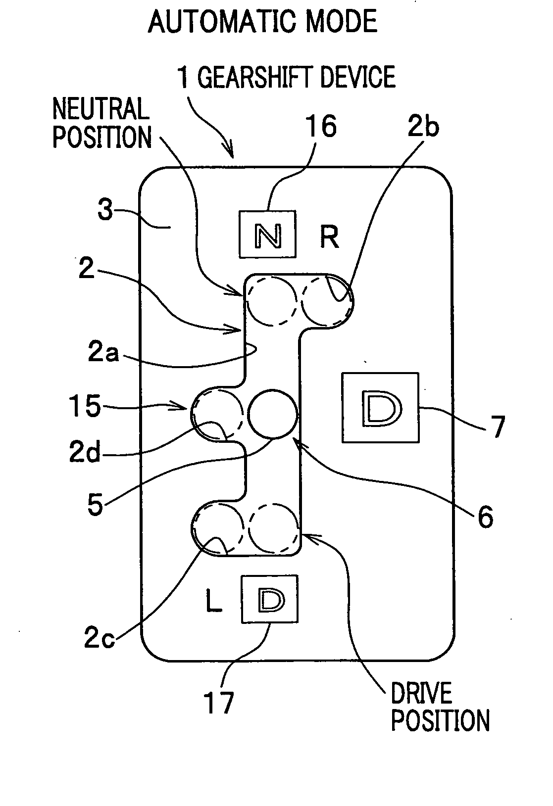
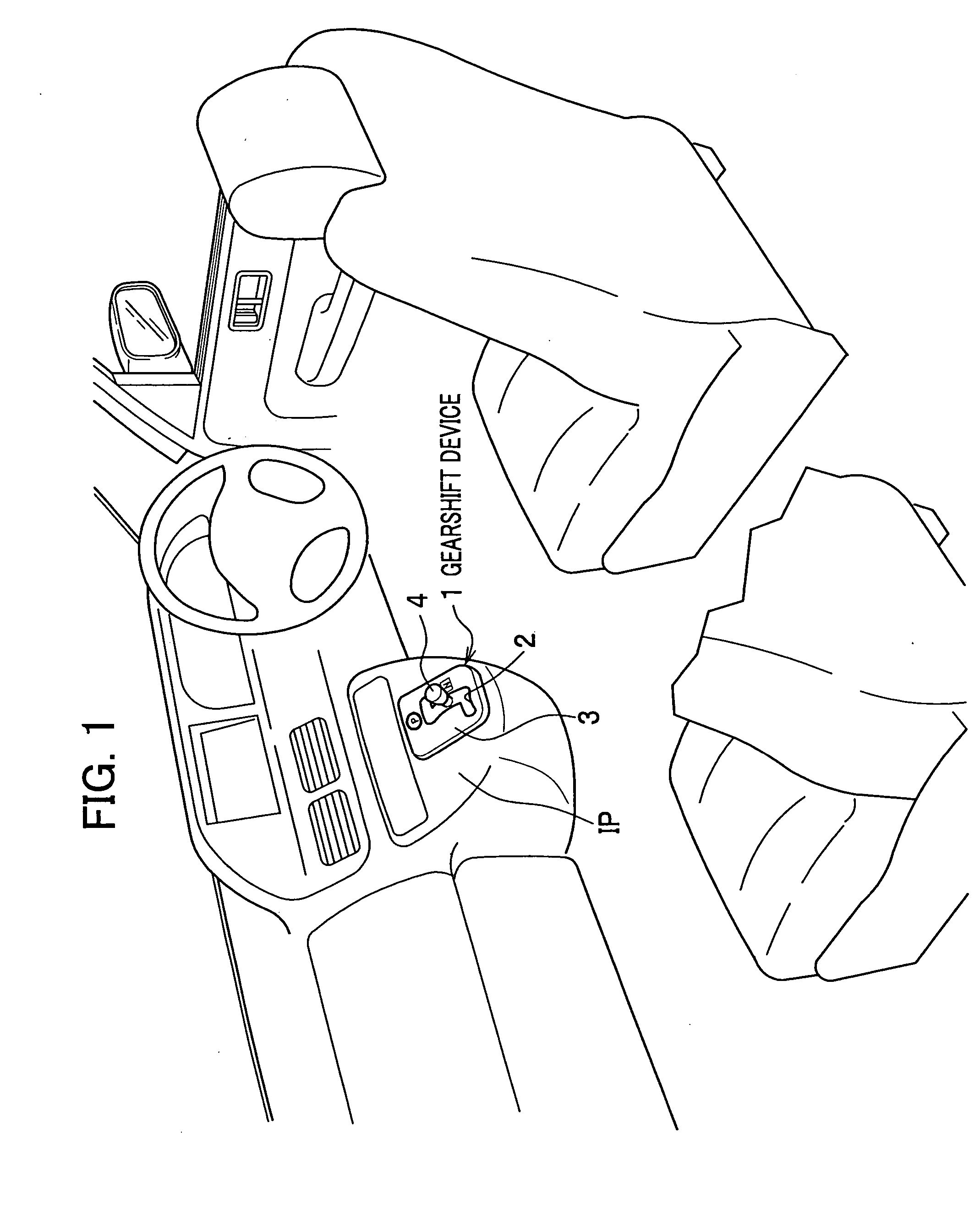
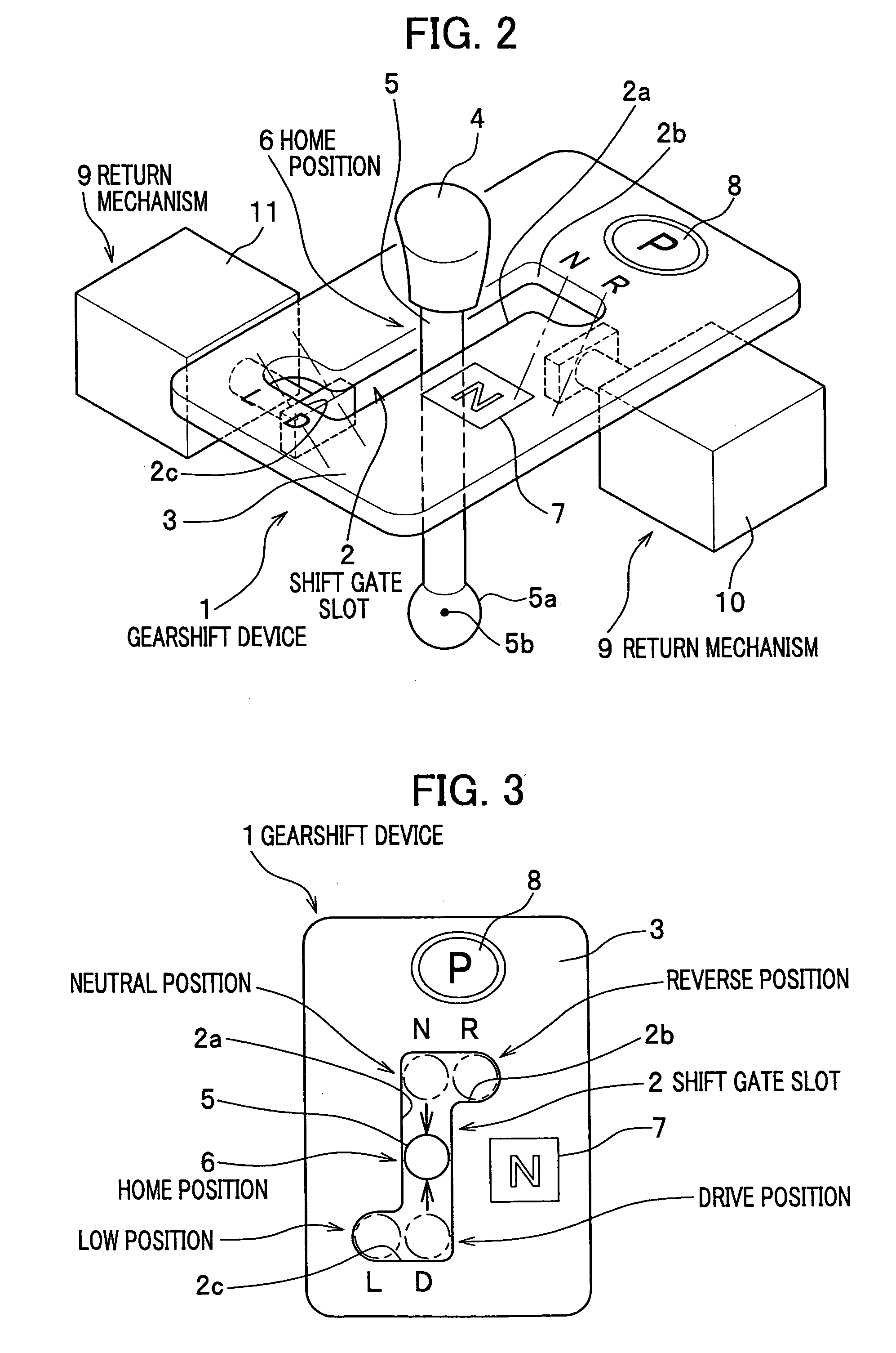
[0033] A description will be given of exemplary embodiments of the present invention with reference to the drawings. Referring now to FIGS. 1 through 3, a gearshift device 1 according to one embodiment of the present invention is illustrated which is a gearshift device for an automatic transmission or gearbox (not shown) operated with the “Shift By Wire” scheme. As shown in FIG. 1, the gearshift device 1 is mounted in an instrument panel IP provided for example between the driver's seat and a passenger seat next to the driver's seat. In this embodiment, a shift gate slot 2 is provided in an escutcheon cover 3 attached to the instrument panel IP; however, the shift gate slot 2 may be provided directly in the instrument panel IP.

[0034] As shown in FIG. 2, a shift lever 5 having a shift knob 4 attached at its upper end is inserted in the shift gate slot 2. At a lower end of the shift lever 5 is provided a spherical pivot ball portion 5, which is supported by a spherical bearing (not s...


PUM


Abstract

In an automatic transmission, a shift lever is operable to move to one of a plurality of shift positions corresponding to ranges established as selectable options. The plurality of shift positions are each configured as one of a momentary position allowing the shift lever to automatically return to a home position and a retention position allowing the shift lever to be held therein. A return mechanism for causing the shift lever held in the retention position to return to the home position is provided. The return mechanism is enabled on one of conditions that the parking switch be turned on and that an ignition switch be turned off. In a manual transmission, a return mechanism for causing the shift lever held in a gear stage to return to a home position is provided, and the return mechanism is enabled on condition that an ignition switch be turned off.

Description

BACKGROUND OF THE INVENTION [0001] This invention relates to a gearshift device for a system for transmission of power in a motor vehicle, and a method of controlling the same. [0002] Among various types of gearshift devices for an automated speed changing mechanism or automatic transmission (gearbox) provided in a vehicle, those which adopt so-called “Shift By Wire” scheme have been attracting attention in recent years as carrying advantages in downsizing of the device and reduction in the force required for operation thereof. JP 2002-254942 A (see Paragraphs 0020-0029, FIG. 2) and JP2003-327002 (see Paragraphs 0013-0017, FIG. 2) disclose exemplary implementations of such “Shift By Wire” type gearshift devices. The gearshift device adopting the “Shift By Wire” scheme is, in general, configured to switch gears in the automatic transmission using an actuator, based upon the position of a shift lever detected using a sensor or the like; that is, the gears of the automatic transmission...

Claims


Application Information

Patent Timeline
Patent Type & Authority Applications(United States)
IPC IPC(8): B60K20/00F16H59/10F16H59/74F16H61/22F16H63/42
CPCF16H59/10F16H61/22F16H63/42Y10T74/20067F16H2059/746F16H2061/168Y10T74/20018F16H2059/0295
Inventor MORITA, AKIOOHKAWA, YASUSHISAITO, YOSHIHARUSAKURABA, TOMOHIROKOMATSU, ATSUSHIHIRAMINE, KOTARONOGUCHI, SHUSAKUFURUSAWA, YOSHINORIISHIMOTO, MAKIROU
Owner HONDA MOTOR CO LTD
Why Eureka
Try Eureka