Face mask

a face mask and mask technology, applied in the field of face masks, can solve the problems of insufficient amount of breathable gas or aerosol drug to be and achieve the effect of reducing the amount of breathable gas or aerosol drug inhaled by the wearer

Inactive Publication Date: 2006-03-16
MESURE TECH
View PDF19 Cites 15 Cited by
  • Summary
  • Abstract
  • Description
  • Claims
  • Application Information

AI Technical Summary

Problems solved by technology

Therefore, the substantial amount of the breathable gas or aerosol drug to be inhaled by the wearer is not enough since the concentration of the breathable gas or aerosol drug is diluted with the exhalation gas.

Method used


Image

  • Face mask
  • Face mask
  • Face mask

Examples


Embodiment Construction

[0011] Various aspects of the system and method of the present invention will be described, and for purposes of explanation, specific configurations and details are set forth in order to provide a thorough understanding of the present invention. However, it will be apparent to one skilled in the art that the present invention may be practiced without these specific details. Furthermore, well known features have been omitted or simplified in order to prevent obscuring the present invention.

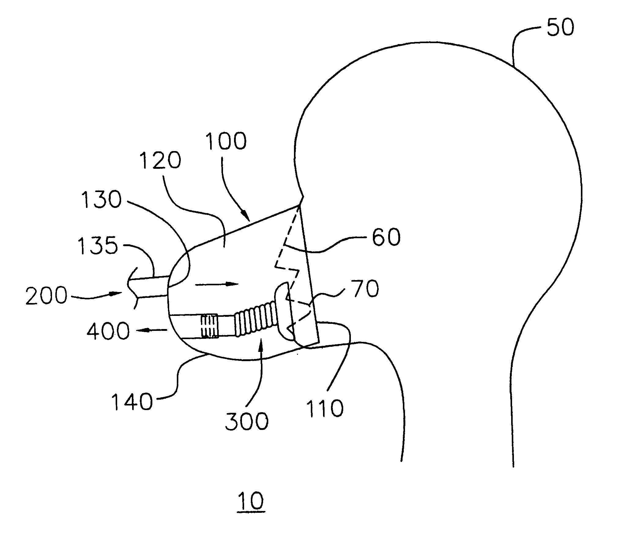
[0012]FIG. 1 illustrates the face of a wearer 50 such as a person or a patient, and the nose 60 and the mouth 70 covered by a face mask 10, according to an exemplary embodiment of the present invention. A body 100 of the face mask 10 includes a peripheral edge 110 for placement against the face. The peripheral edge 110 of the body defines a single chamber 120 over the nose 60 and the mouth 70 of the wearer. The body 100 is typically made of a flexible material, such as a thermoplastic, e.g., PVC m...


PUM


Abstract

A face mask for use in gas delivery applications, such as breathable gas or aerosol drug systems. The face mask includes a body having a peripheral edge for placement against the face of a wearer. The peripheral edge defines a single chamber over the nose and the mouth of the wearer. An inlet opening is formed on a surface of the body for supplying inhalation gas to the nose through the chamber. A vent assembly inwardly extends from the surface of the body to the chamber and seals around the mouth for passing exhalation gas to the exterior of the body.

Description

BACKGROUND OF THE INVENTION [0001] The invention relates to the field of face masks. More particularly, the invention relates to the field of face masks for use in gas delivery applications. [0002] In traditional face mask design, breathable gas or aerosol drug is directly delivered into a chamber of the face mask, while at the same time, the exhalation gas generated from the nose or the mouth of the wearers will enter into the chamber. Therefore, the substantial amount of the breathable gas or aerosol drug to be inhaled by the wearer is not enough since the concentration of the breathable gas or aerosol drug is diluted with the exhalation gas. SUMMARY OF THE INVENTION [0003] An exemplary embodiment of the present invention overcomes the above-described problems by providing face masks that could directly pass exhalation gas to the exterior of body thereof. [0004] An exemplary embodiment of the invention provides a face mask for use in gas delivery applications, such as breathable g...

Claims


Application Information

Patent Timeline
Patent Type & Authority Applications(United States)
IPC IPC(8): A62B18/08A61M16/06A62B9/00
CPCA61M16/06
Inventor YU, CHU-YIH
Owner MESURE TECH
Why Eureka
Try Eureka