Ball ramp caliper brake

a caliper brake and ball-type technology, applied in the field of brakes, can solve the problems of limiting the manufacture method of bridges, lack of efficiency, and bending moment of braking force applied, and achieve the effect of improving the wear of the brake pads, efficient and less costly construction

Active Publication Date: 2006-03-16
LAMBERT BRAKE
View PDF9 Cites 0 Cited by
  • Summary
  • Abstract
  • Description
  • Claims
  • Application Information

AI Technical Summary

Benefits of technology

[0006] It is another object of the present invention to provide a brake assembly, as above, which improves the wear on the brake pads.
[0007] It is a further object of the present invention to provide a brake assembly, as above, which is efficient and less costly to construct.

Problems solved by technology

This causes a bending moment when braking force is applied.
Also, the bending moment causes uneven wear of the pads and results in a lack in efficiency.
In addition, not having the bridge at the geometric center of the braking force limits the methods of manufacture of the bridge.

Method used


Image

  • Ball ramp caliper brake
  • Ball ramp caliper brake
  • Ball ramp caliper brake

Examples


Embodiment Construction

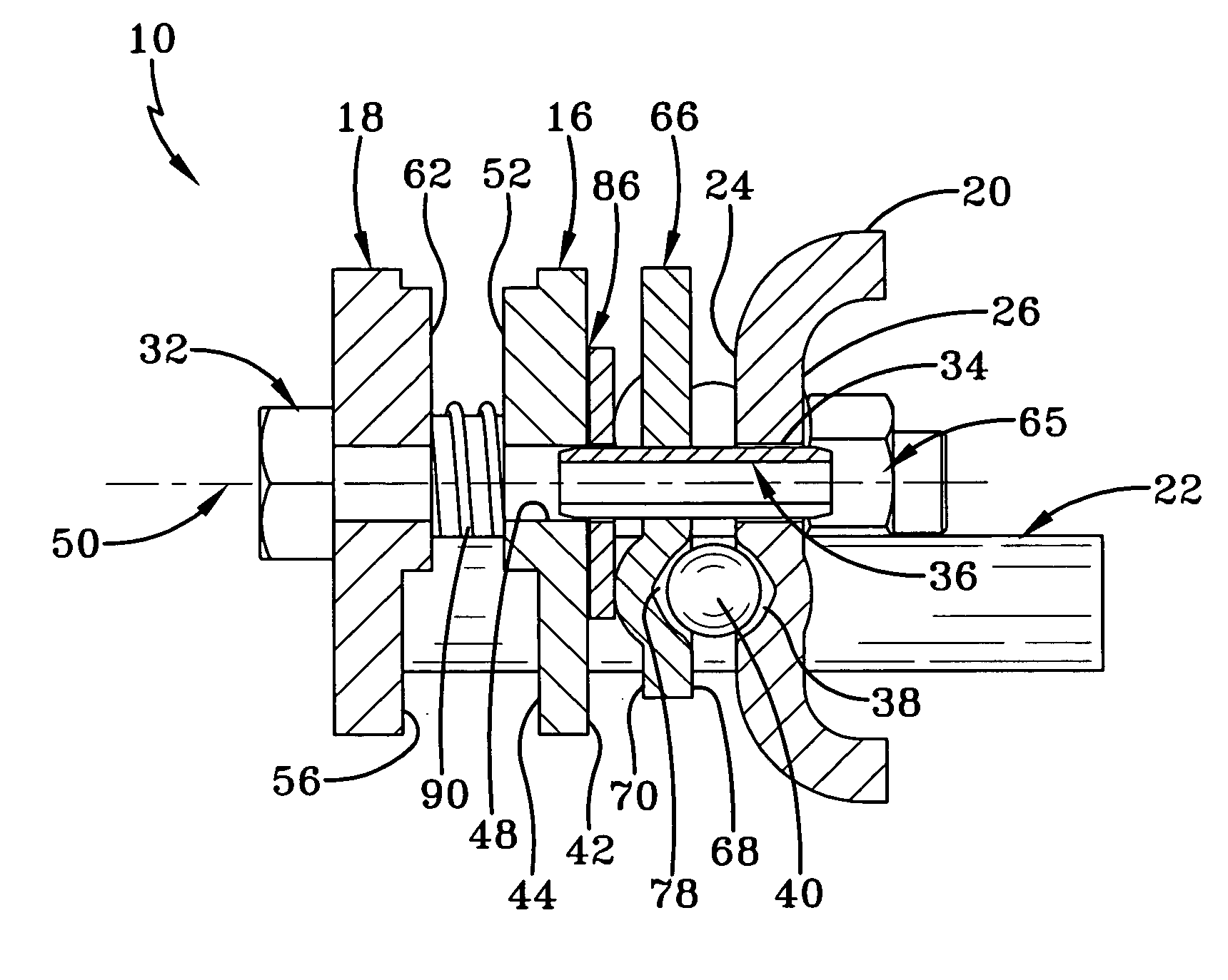
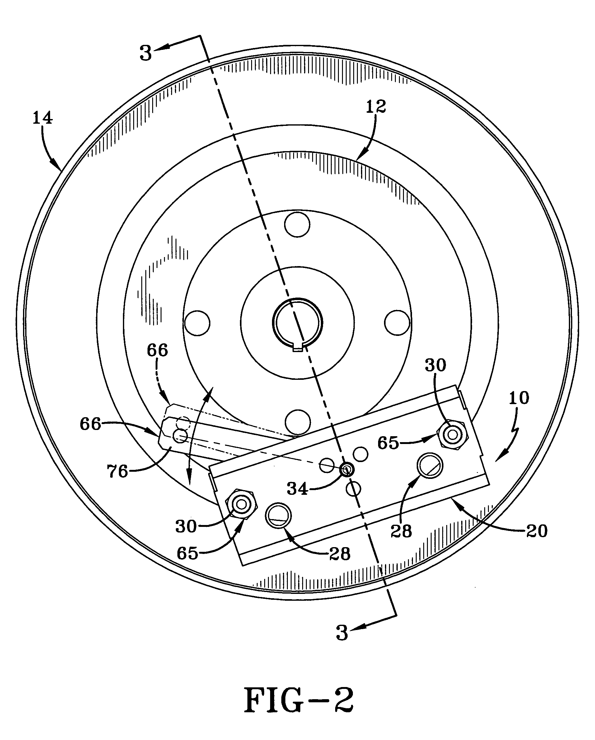
[0018] A brake assembly made in accordance with the present invention is indicated generally by the numeral 10. Referring to FIGS. 2 and 3, brake 10 is shown as being held at a constant radial position relative to a rotor 12 which is coupled to a wheel hub 14. When brake assembly 10 is actuated, a first stator 16 and a second stator 18, located on opposed sides of rotor 12, apply opposed coaxial pressure to the spinning rotor 12. Because brake assembly 10 is held rotationally stationary relative to rotor 12, torque is transferred from spinning rotor 12 to the vehicle frame (not shown), thereby braking the vehicle.

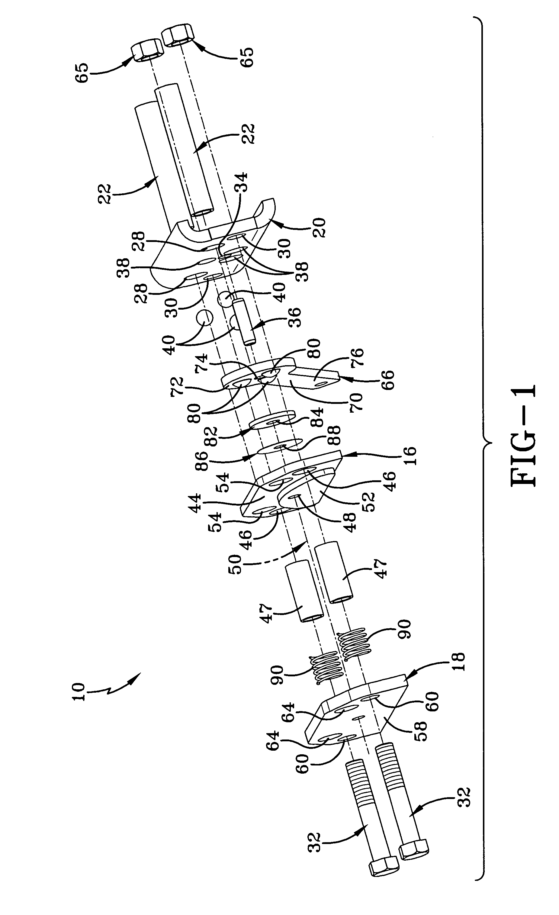
[0019] Referring now to FIGS. 1 and 4, brake assembly 10 includes a stationary actuator 20 which is generally shaped in an elongated “C” and mounts to the vehicle frame via a pair of mounting sleeves 22, as will hereinafter be discussed in more detail. Actuator 20 has a first surface 24 facing rotor 12 and a second surface 26 facing the vehicle frame. Actuator 20 is provid...


PUM


Abstract

A brake (10) for a wheel of a vehicle is slidably mounted to a vehicle frame by mounting sleeves (22). The brake (10) includes a stationary actuator (20) which has a plurality of depressions (38) adapted to receive a plurality of balls (40). The stationary actuator (20) further has a pin hole (34) which receives a pin (36) which correspondingly defines a pivot axis (50). Adjacent to the stationary actuator (20) is a rotating actuator (66) which rotates about an axis (50) and includes a plurality of depressions (78) which are axially aligned with the depressions (38) while in an unactuated state. The brake (10) is actuated by rotation of the rotating actuator (66) which correspondingly moves the balls (40) to progressively more shallow portions of the depressions (38, 78) which acts upon a washer (82) and one or more shims (86) to force a first stator (16) and a second stator (18) together and into contact with a rotor (12). The stators (16, 18) are biased apart by the bridge springs (90) and are axially located by a pair of bridge sleeves (30) such that the axes of the bridge sleeves (30) are coplanar with the axis (50).

Description

TECHNICAL FIELD [0001] This invention relates to a brake especially adapted for use with zero turn mowers and small utility vehicles, such as golf carts and the like. More specifically, this invention relates to such a brake wherein the actuating mechanism is a ball ramp having bridges located in the center of the geometric applied load. BACKGROUND ART [0002] Utility vehicles such as golf carts require small braking assemblies that provide adequate braking power with minimal input force. One such method for providing such a braking force is through the use of caliper disc braking assemblies that use ball ramp actuators. Typically, a ball ramp actuated brake includes several metal balls, sandwiched between a ramp plate and a stationary plate. The ramp and stationary plate include ramped depressions within which the balls reside. The balls are located in a circular pattern about a central pivot axis. If braking torque is desired, the operator causes the ramp plate to rotate about that...

Claims


Application Information

Patent Timeline
Patent Type & Authority Applications(United States)
IPC IPC(8): F16D55/08
CPCF16D55/2255F16D2125/36F16D2121/14
Inventor DENNIS, BRIAN P.BALDEOSINGH, HOWARD H.
Owner LAMBERT BRAKE
Why Eureka
Try Eureka