Driving device

a technology of driving device and movable member, which is applied in the direction of piezoelectric/electrostrictive/magnetostrictive devices, piezoelectric/electrostriction/magnetostriction machines, electrical apparatus, etc., can solve the problem of difficult to achieve stable increase in velocity against dispersion, low velocity of movable member,

Inactive Publication Date: 2006-03-16
KONICA MINOLTA INC
View PDF16 Cites 10 Cited by
  • Summary
  • Abstract
  • Description
  • Claims
  • Application Information

AI Technical Summary

Benefits of technology

[0035] In the driving device having this configuration, the current-detecting circuit for detecting as voltage a current flowing through the electromechanical transducer element and the amplifier circuit for amplifying the voltage detected by the current-detecting circuit are provided in the driving circuit, and thus a frequency of the drive voltage that is applied to the electromechanical transducer element coincides with a resonance frequency of the electromechanical transducer element at all times. Besides, the outflow-current-limiting circuit for limiting a current that flows out from the amplifier circuit and the inflow-current-limiting circuit for limiting a current that flows into the amplifier circuit are provided in the driving circuit, and thus the drive voltage that is applied to the electromechanical transducer element is distorted so as to have a sawtoothed waveform. As a result, the electromechanical transducer element can be driven constantly by the sawtoothed drive voltage having the resonance frequency, and stable and high-velocity drive of the movable member can be achieved, in spite of initial dispersion of the driving device, fluctuation in environmental temperature, and the like.

Problems solved by technology

Though the prior art described above makes it possible to drive the piezoelectric actuator 1 with use of the simple driving circuit, the prior art has a problem of low velocity of the movable member 20.
In this case, however, the resonance frequencies vary according to initial dispersion of the piezoelectric actuator, environmental temperature and the like, and it is therefore impossible to make fd equal to f1 at all times. Accordingly, it has been difficult to achieve stable increase in the velocity against dispersion resulting from mass production, environmental fluctuation, and the like.

Method used


Image

  • Driving device
  • Driving device
  • Driving device

Examples


Embodiment Construction

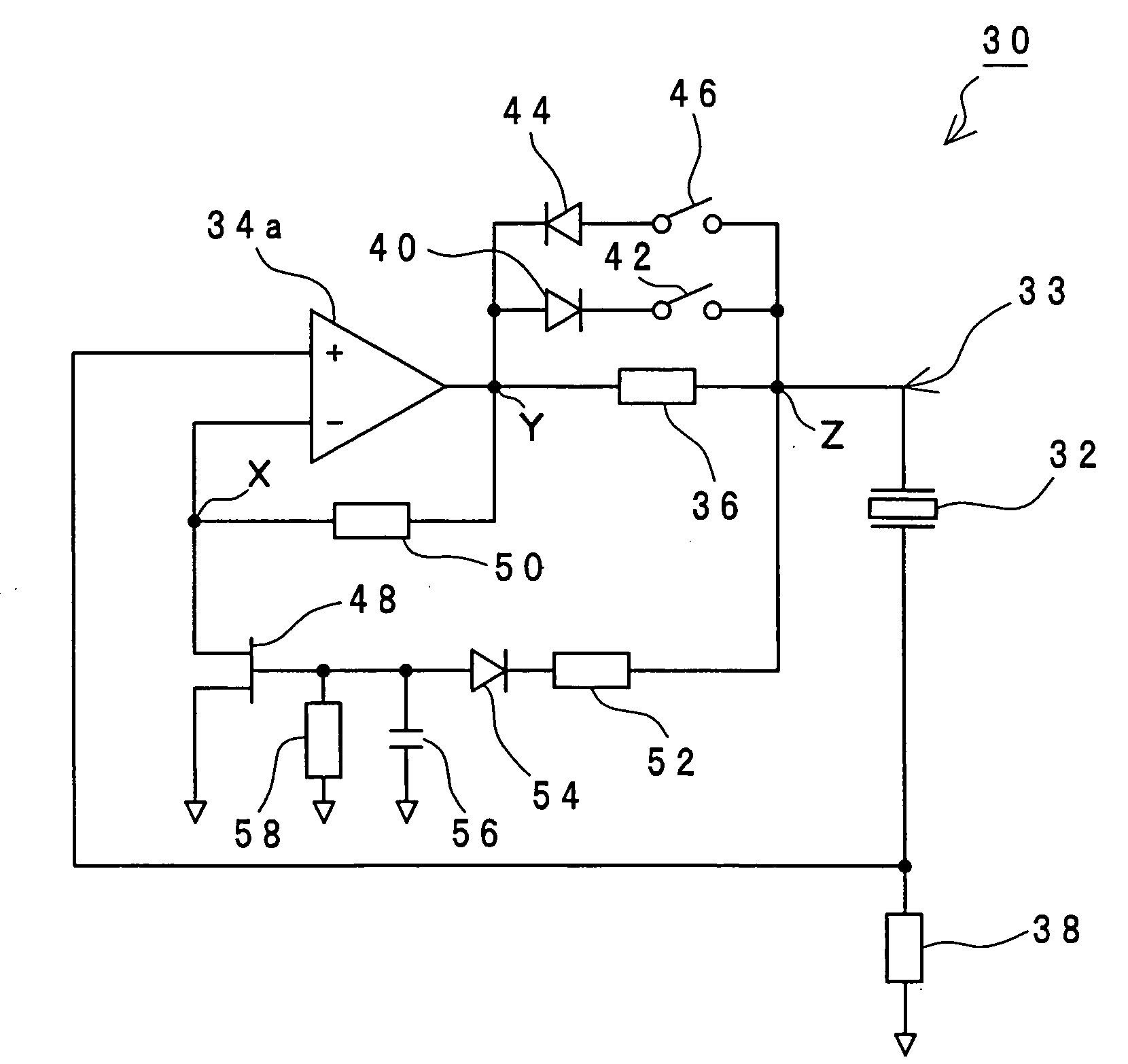
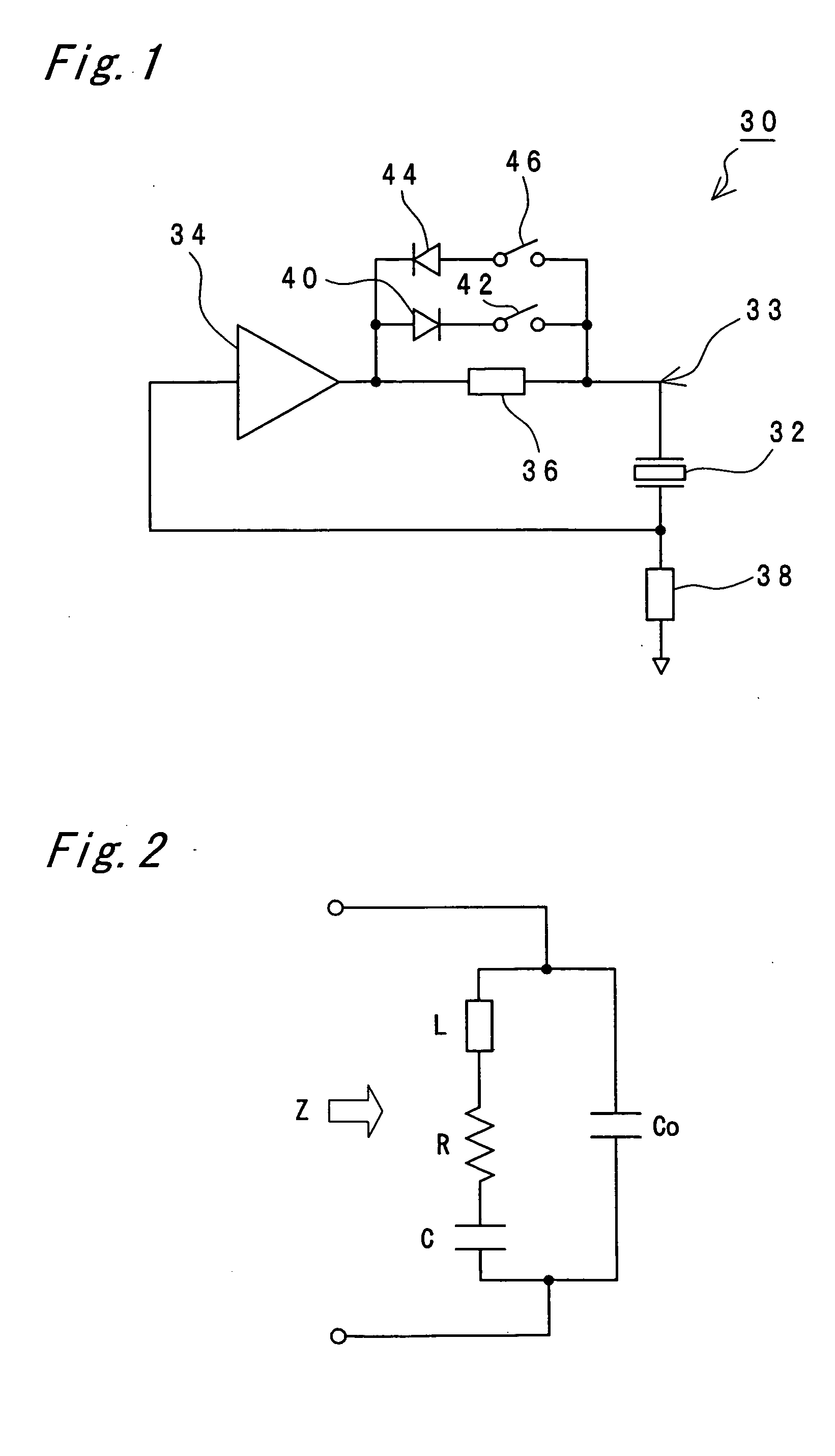
[0049]FIG. 1 is a circuit diagram in principle of a piezoelectric actuator 30 that is one embodiment of a driving device of the invention. The piezoelectric actuator 30 has a piezoelectric element 32 as an electromechanical transducer element. Driving part including the piezoelectric element 32 has a configuration similar to that of the prior art described with reference to FIG. 9. That is, one end of the piezoelectric element 32 is fixed to a supporting member 16. To the other end of the piezoelectric element 32 is fixed a driving shaft (a driving member) 18 shaped like a round bar, for example. On the driving shaft 18 is movably held a movable member 20. The movable member 20 is engaged with the driving shaft 18 with a predetermined frictional force by virtue of a biasing force of an elastic member not shown such as plate spring and coiled spring. On the movable member 20 are mounted lenses or the like that are objects to be driven and that are not shown.

[0050] Across the piezoel...


PUM


Abstract

The driving device has a piezoelectric element 32, a supporting member 16 fixed to one end of the piezoelectric element 32, a driving shaft 18 fixed to the other end of the piezoelectric element 32, a movable member 20 that is movably held on the driving member 18, and a driving circuit 33 that applies the drive voltage to the piezoelectric element 32. The driving circuit 33 includes a self-oscillating circuit 34, 38 that oscillates at a series resonance frequency of the piezoelectric element 32 and a non-linear circuit 36, 40, 42, 44, 46 for adding distortion to the drive voltage that is applied to the piezoelectric element 32.

Description

RELATED APPLICATION [0001] This application is based on Japanese Patent Application No. 2004-269475, the content of which is incorporated herein by reference. BACKGROUND OF THE INVENTION [0002] The present invention relates to a driving device using piezoelectric elements, for example., and particularly relates to a driving device suitable for driving an XY stage, photographic lenses of a camera, projection lenses of an overhead projector, lenses of binoculars, and the like. [0003] Conventionally, e.g., in Japanese Patent Laid-Open Publication No. 2000-350482, a piezoelectric actuator 1 as shown in FIG. 7 has been disclosed. In the piezoelectric actuator 1, a bridge circuit is composed of a piezoelectric element 2 and four FETs (field effect transistors) 4, 6, 8, and 10 connected in series, and signals are inputted from a control circuit 12 into bases of the FETs 4, 6, 8, and 10. A power supply 14 is connected between the FETs 4 and 6, and a ground is established between the FETs 8 ...

Claims


Application Information

Patent Timeline
Patent Type & Authority Applications(United States)
IPC IPC(8): H01L41/09
CPCH02N2/065H02N2/025
Inventor HOSHINO, TAKAYUKI
Owner KONICA MINOLTA INC
Why Eureka
Try Eureka