
Organic electro luminescence display device and fabricating method thereof

a luminescence display and electroluminescence technology, applied in the direction of discharge tube luminescnet screens, discharge tube/lamp details, electric discharge lamps, etc., can solve the problems of deterioration of light emitting efficiency and picture quality of the device, weight and size, etc., to prevent the deterioration of light emitting efficiency and picture quality

Active Publication Date: 2006-03-16
LG ELECTRONICS INC
View PDF4 Cites 9 Cited by
  • Summary
  • Abstract
  • Description
  • Claims
  • Application Information

AI Technical Summary

Benefits of technology

[0017] Accordingly, it is an object of the present invention to provide an organic electro luminescence display device that is adaptive for preventing its light emitting efficiency and picture quality from being deteriorated by way of preventing a sealant from flowing into the organic electro luminescence display device, and a fabricating method thereof.

Problems solved by technology

Recently, there have been developed a variety of flat panel display devices that can reduce their weight and size, which are a disadvantage of a cathode ray tube CRT.
Accordingly, there is a problem in that the light emitting efficiency and picture quality of the device is deteriorated.

Method used


Image

  • Organic electro luminescence display device and fabricating method thereof
  • Organic electro luminescence display device and fabricating method thereof
  • Organic electro luminescence display device and fabricating method thereof

Examples


Embodiment Construction

[0033] Reference will now be made in detail to the preferred embodiments of the present invention, examples of which are illustrated in the accompanying drawings.

[0034] With reference to FIGS. 5 to 7F, embodiments of the present invention will be explained as follows.

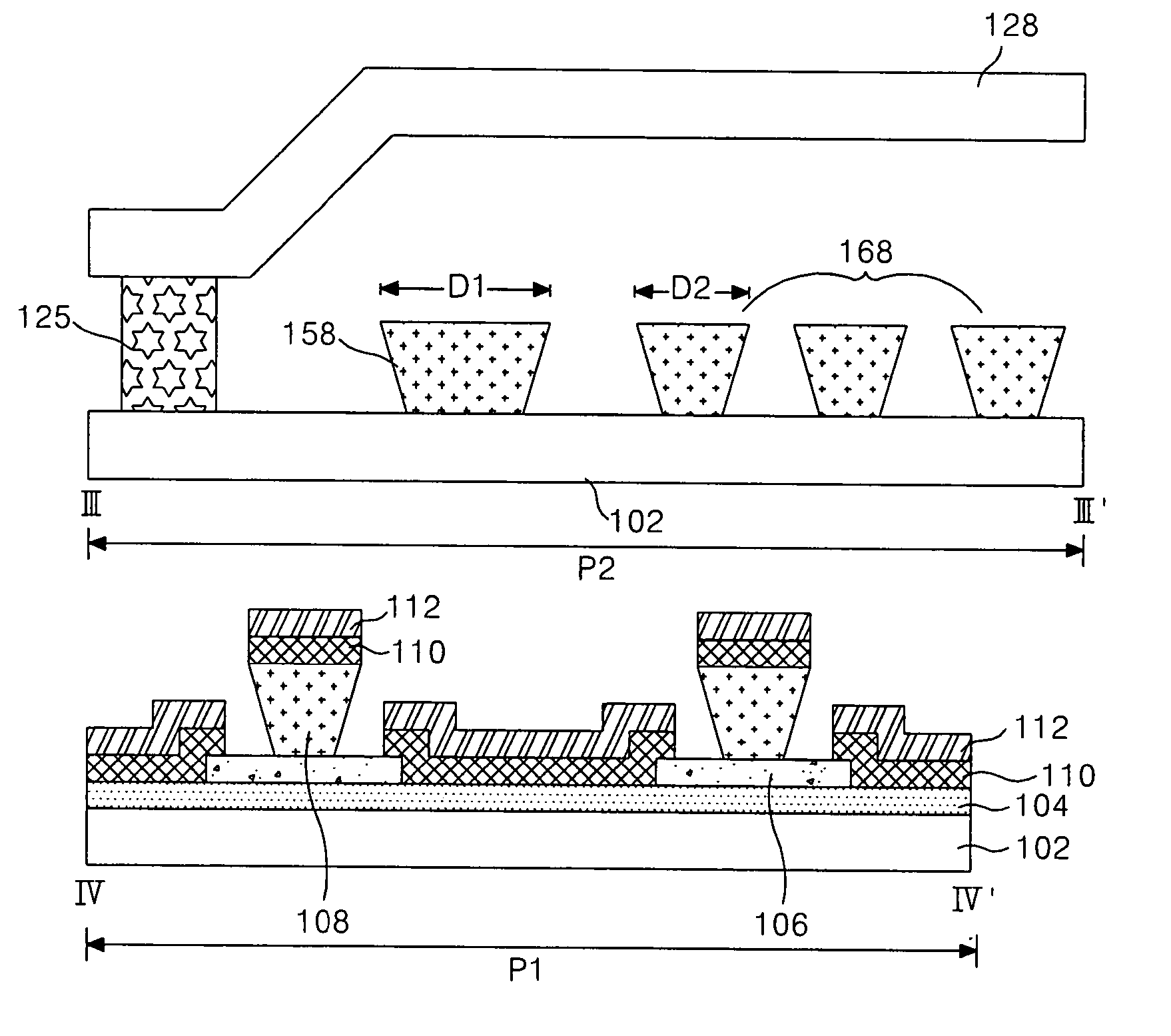
[0035]FIG. 5 is a diagram representing part of an organic EL display device according to an embodiment of the present invention, and FIG. 6 is a sectional diagram illustrating the organic EL display device taken along the lines III-III′ and IV-IV′ shown in FIG. 5.

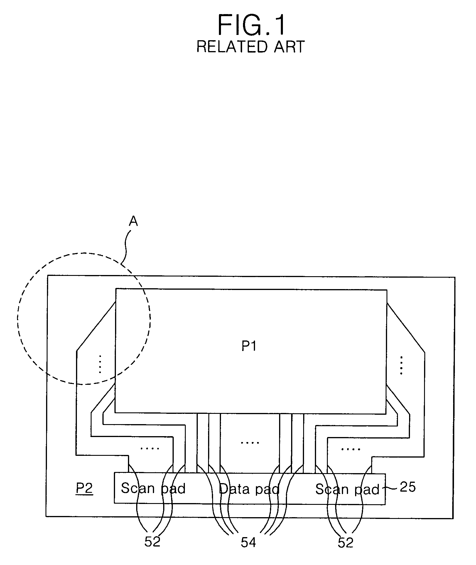
[0036] The organic EL display device shown in FIGS. 5 and 6 includes a display area P1 where an organic EL array inclusive of an anode electrode and so on is formed, and a non-display area P2 where a pad part supplying driving signals to driving electrodes of the display area P1 is located.

[0037] In the display area P1, there is formed the organic EL array which includes an anode electrode 104 formed on a substrate 102 and a cathode electrode 112 formed in ...


PUM


Abstract

There is disclosed an organic electro luminescence display device that is adaptive for preventing the deterioration of its light emitting efficiency and picture quality, and a fabricating method thereof. An organic electro luminescence display device according to an embodiment of the present invention includes an organic electro luminescence array having first and second electrodes formed on a substrate with an organic light emitting layer therebetween, and a barrier rib in parallel to anyone of the first and second electrodes; a protective barrier rib formed to enclose the organic electro luminescence array; and at least one dummy barrier rib located inside a corner area of the protective barrier rib and formed to be bent along the protective barrier rib.

Description

[0001] This application claims the benefit of the Korean Patent Application No. P2004-73282 filed on Sep. 14, 2004, which is hereby incorporated by reference. BACKGROUND OF THE INVENTION [0002] 1. Field of the Invention [0003] The present invention relates to an organic electro luminescence display device, and more particularly to an organic electro luminescence display device that is adaptive for preventing the deterioration of its light emitting efficiency and picture quality, and a fabricating method thereof. [0004] 2. Description of the Related Art [0005] Recently, there have been developed a variety of flat panel display devices that can reduce their weight and size, which are a disadvantage of a cathode ray tube CRT. The flat panel display device includes a liquid crystal display LCD, a field emission display FED, a plasma display panel PDP and an electro luminescence EL display device. [0006] Studies for increasing the picture quality and the size of the screen of the flat pa...

Claims


Application Information

Patent Timeline
IPC IPC(8): H01J1/62H01J63/04
CPCH01L27/3223H01L51/5246H01L27/3283H10K59/88H10K59/173H10K59/8722H05B33/22H05B33/10H10K50/8426
Inventor BAIK, KWANG HEUMRUM, DO YOUNGKIM, KI HONGLEE, JUNG HWAN
Owner LG ELECTRONICS INC
Learn More