Organic-electroluminescence display and driving method therefor

a technology of organicelectroluminescence and driving method, which is applied in the direction of electroluminescent light sources, static indicating devices, instruments, etc., can solve the problems of lowering contrast, achieve lowering picture quality, preventing the effect of lowering contras

Inactive Publication Date: 2006-03-16
HITACHI DISPLAYS
View PDF22 Cites 32 Cited by
  • Summary
  • Abstract
  • Description
  • Claims
  • Application Information

AI Technical Summary

Benefits of technology

[0014] If the luminance of the high-luminance and small-area portion is lowered to 80% from the beginning, the contrast is lowered. This results in a lowering in picture quality. In the present invention, however, the portion is displayed with the 100-% luminance at the beginning. This condition prevents the contrast from being lowered. Next, the luminance is lowered in a little-by-little manner with the time spent. This condition prevents the feeling of a sense of the contrast lack unlike the case where the 80-% luminance is displayed from the beginning.

Problems solved by technology

In this case, however, there has existed a problem that the contrast will be lowered.

Method used


Image

  • Organic-electroluminescence display and driving method therefor
  • Organic-electroluminescence display and driving method therefor
  • Organic-electroluminescence display and driving method therefor

Examples


Embodiment Construction

[0028] Hereinafter, referring to the drawings, the detailed explanation will be given below concerning embodiments of the present invention.

[0029] Incidentally, in all of the drawings for explaining the embodiments, one and the same reference numeral is allocated to a configuration component having one and the same function. Accordingly, the repeated explanation thereof will be omitted.

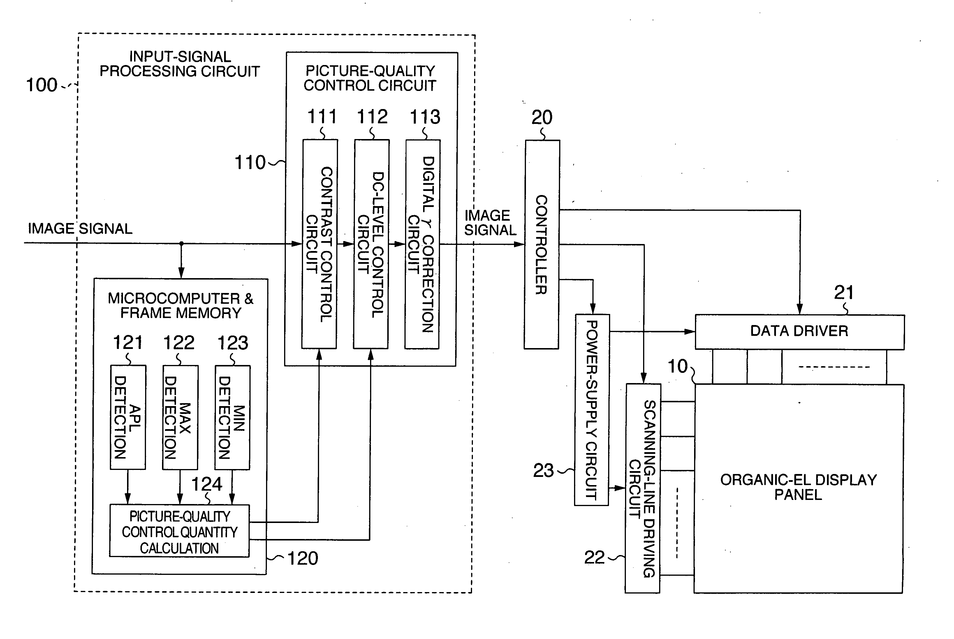
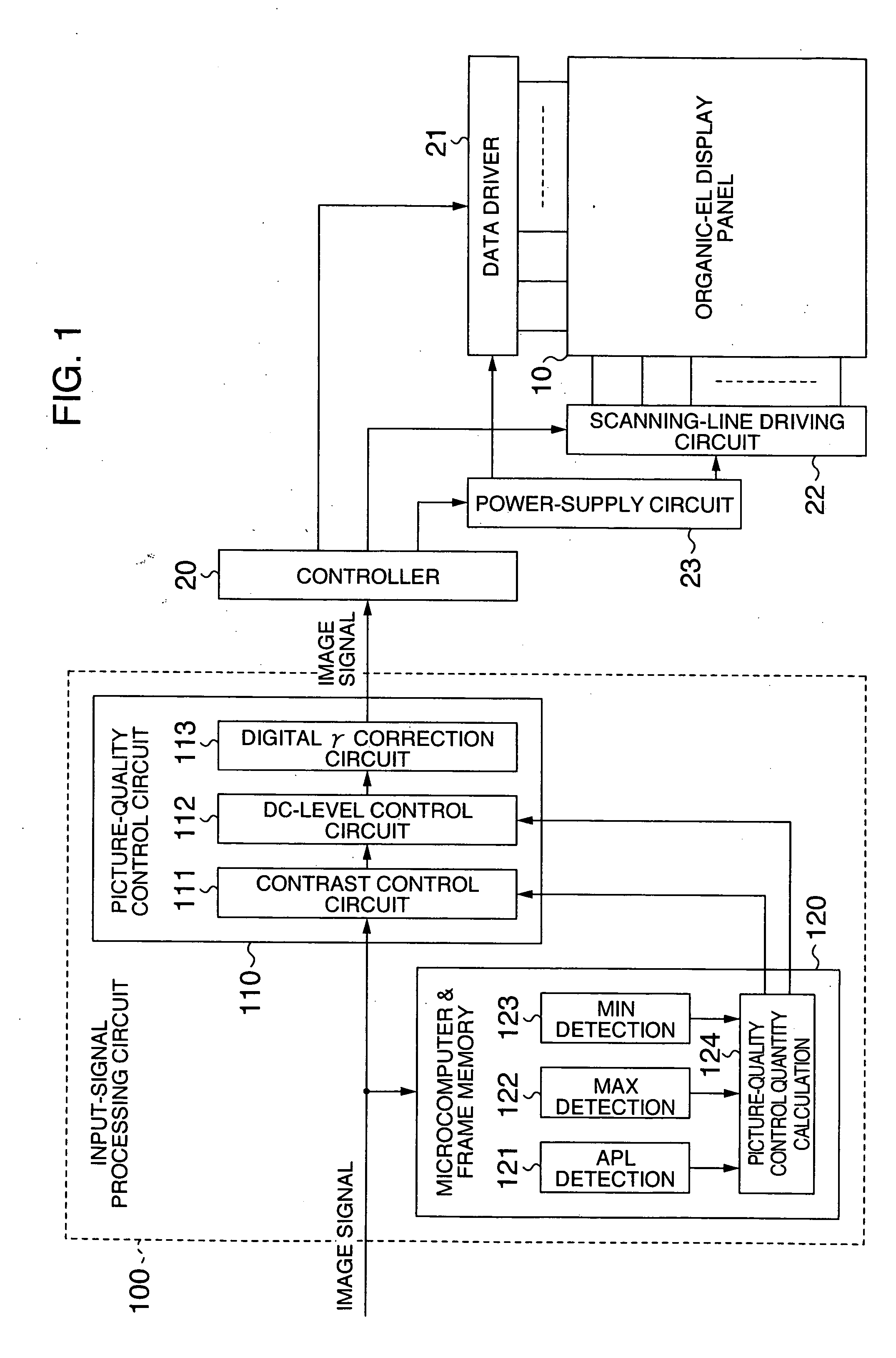
[0030]FIG. 1 is a block diagram for illustrating the schematic configuration of an organic-EL display device in an embodiment of the present invention.

[0031] The organic-EL display device of the present invention includes the following configuration components: An organic-EL display panel 10, a data driver 21 and a scanning-line driving circuit 22 located or formed on the periphery thereof, a controller 20 for controlling the data driver 21 and the scanning-line driving circuit 22, and an input-signal processing circuit 100. Here, in the input-signal processing circuit 100, an image signal inputted...


PUM


Abstract

In a method of driving an organic-electroluminescence display device, when a small white pattern is displayed at the same position of the black background for a long time, burn-in of the white-pattern displayed portion is prevented without a feeling of a sense of the contrast lack. The organic-electroluminescence display device includes an organic-electroluminescence element panel, and an input-signal processing circuit into which an image signal is to be input. The input-signal processing circuit includes a luminance detection circuit for detecting average luminance of the input image signal, and a luminance control circuit. The luminance control circuit, when, as an image on the organic-electroluminescence element panel, a high-luminance pattern continues to be displayed longer than a time-interval T1 on a low average-luminance screen, lowers the luminance of the pattern down to a predetermined value with a time-interval T2 after T1.

Description

INCORPORATION BY REFERENCE [0001] The present application claims priority from Japanese application JP2004-227701 filed on Aug. 4, 2004, the content of which is hereby incorporated by reference into this application. BACKGROUND OF THE INVENTION [0002] 1. Field of the Invention [0003] The present invention relates to an organic-electroluminescence display device using organic-electroluminescence (EL; Electro Luminescence) elements, and a driving method therefor. More particularly, it relates to a technology for preventing burn-in at the time of displaying a small white pattern at the same position of the black background for a long time. [0004] 2. Description of the Related Art [0005] An active-matrix-driven organic-electroluminescence display device (which, hereinafter, will be referred to as “organic-EL display”) using organic-electroluminescence elements (hereinafter, referred to as “organic-EL elements”) is expected as the next-generation flat panel display. [0006] As described i...

Claims


Application Information

Patent Timeline
Patent Type & Authority Applications(United States)
IPC IPC(8): G09G3/10H05B44/00
CPCG09G3/3233G09G3/3241G09G2300/0819G09G2300/0842G09G2300/0852G09G2360/16G09G2320/043G09G2320/046G09G2320/066G09G2330/02G09G2300/0861
Inventor SHINGAI, AKIRAFUJIHIRA, MASAHITOTOKUDA, NAOKI
Owner HITACHI DISPLAYS
Why Eureka
Try Eureka