Antenna with built-in filter

a filter and built-in technology, applied in the structure of radiating elements, resonant antennas, substantially flat resonant elements, etc., can solve the problems of reducing the characteristic of transmitting and receiving, deteriorating (increasing noise), and small coupling between each other, and achieve high performan

Inactive Publication Date: 2006-03-16
UBE IND LTD
View PDF8 Cites 190 Cited by
  • Summary
  • Abstract
  • Description
  • Claims
  • Application Information

AI Technical Summary

Benefits of technology

[0011] According to this construction, the feeding terminal electrode faces only to a circuit board on which the antenna with built-in filter is mounted and a multi-layer laminate structure in which a shielding plate is embedded can be used for the circuit board, whereby the feeding terminal electrode can be connected to a feeder of the circuit board as it is perfectly shielded. Consequently, external noise is not directly carried on the feeding terminal electrode, and even if a signal of other frequency band appears on the feeding terminal electrode, it is not coupled to a receiving circuit of different frequency band. As a result, isolation property between the feeding terminal electrode and the electronic circuit on the circuit board is extremely enhanced, and further, there is no fear of reducing characteristic of a desired transmitting or receiving signal, thereby obtaining an extremely high-performance antenna with built-in filter.
[0013] The mounting structure of the antenna with built-in filter according to the present invention comprises; the antenna with built-in filter of claim 1 and a circuit board having a laminated structure including at least a shielding layer and a wiring layer, on which the antenna is mounted, wherein the feeding terminal electrode is electrically connected to an internal wiring provided in the circuit board and an electronic device provided on a surface of the circuit board is electrically connected to the feeding terminal electrode via the internal wiring. This structure makes it possible to use the internal wiring for a feeder that is electrically connected to the feeding terminal electrode. Therefore, the feeding terminal electrode can be connected to a component constituting the electronic circuit with a state that it is not at all exposed to the outside and it is shielded by a shielding plate, thereby being capable of providing a transmitter or a receiver with extremely high performance.

Problems solved by technology

The feeding terminal electrode and these electronic circuits are electromagnetically coupled, with the result that the noise or a signal of the other frequency band picked up by the feeding terminal electrode interferes directly with the circuits on the circuit board, thereby entailing a problem of deteriorating (increasing noise) isolation property (meaning that the coupling between each other is small) or reducing transmit-receive characteristic.

Method used


Image

  • Antenna with built-in filter
  • Antenna with built-in filter
  • Antenna with built-in filter

Examples


Embodiment Construction

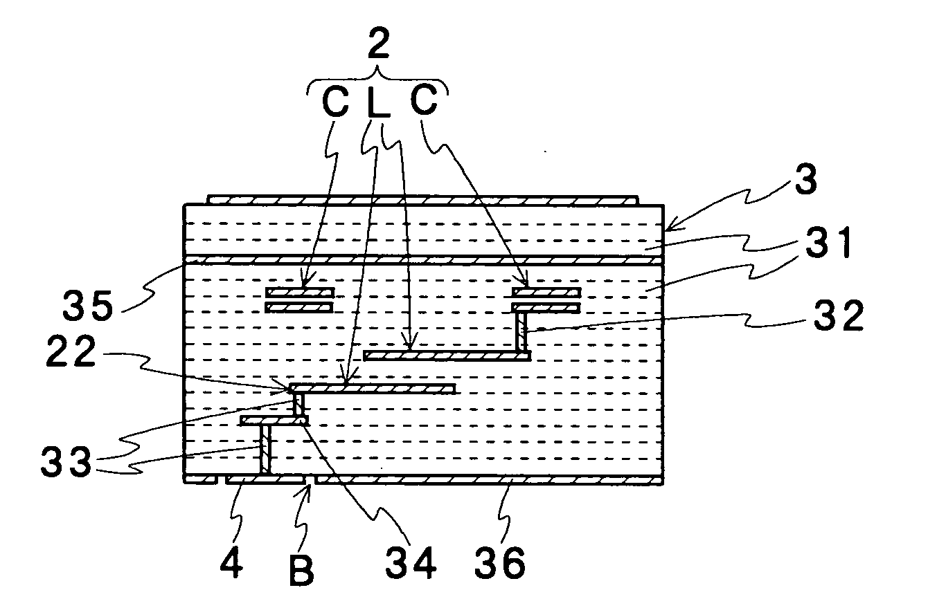
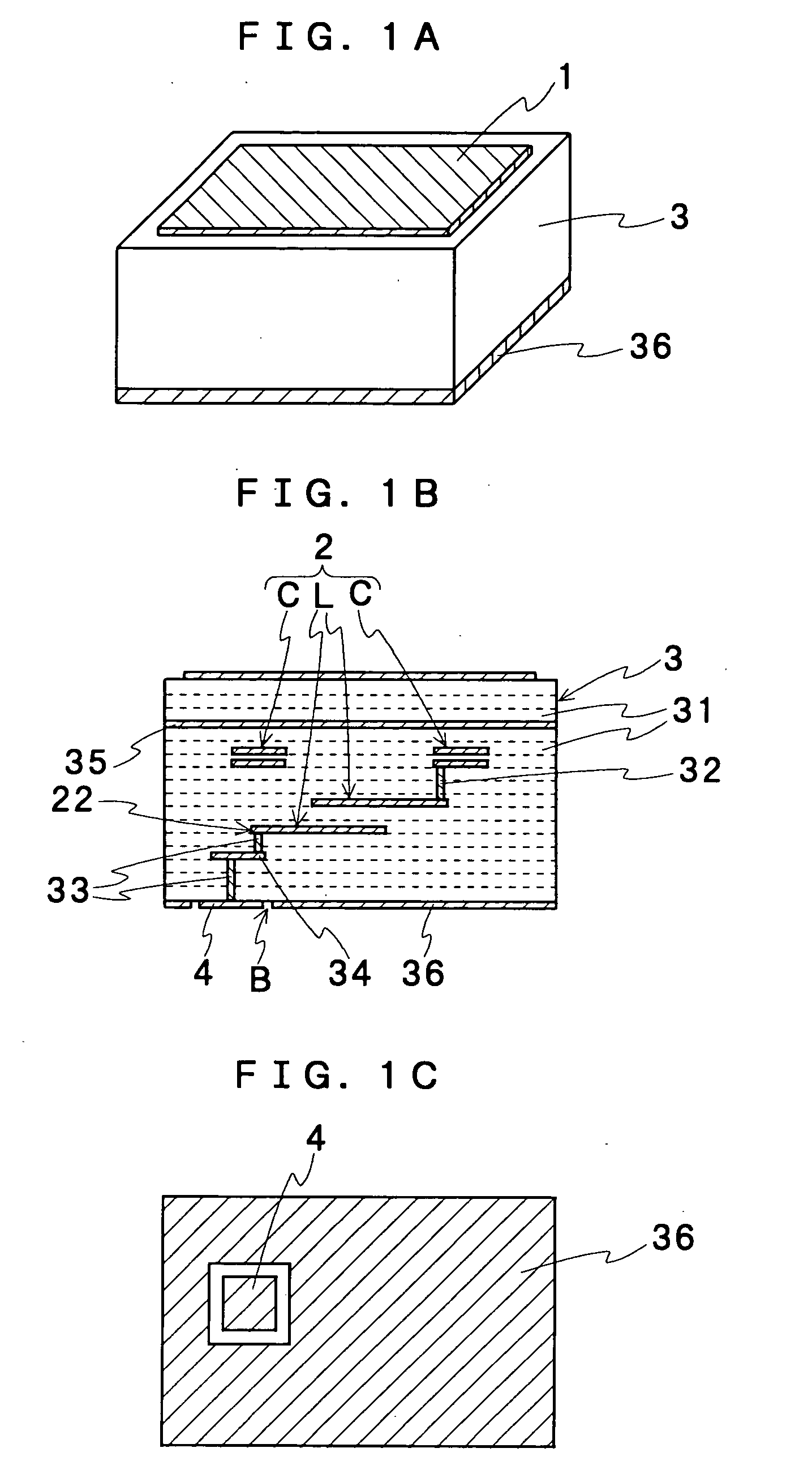
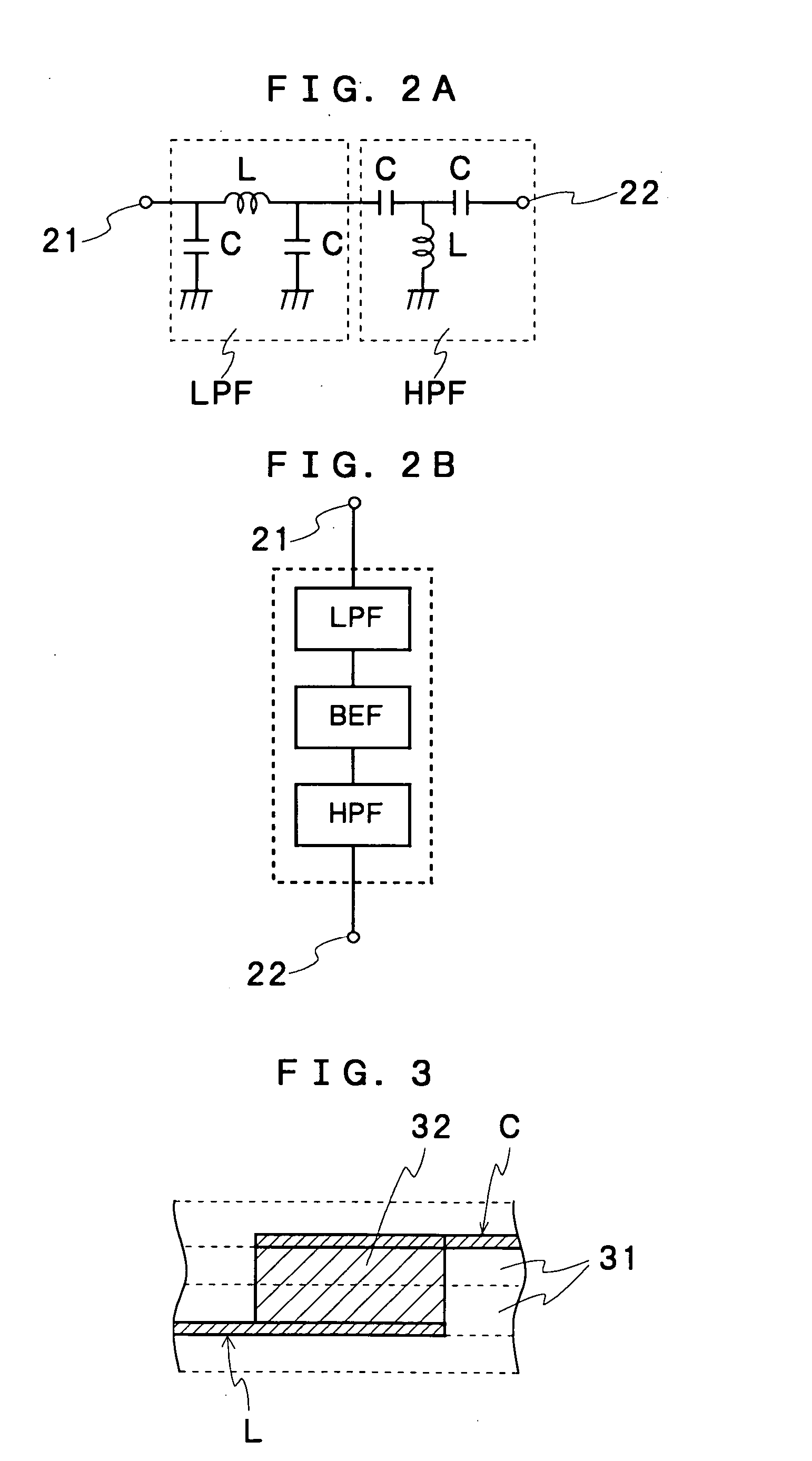
[0021] Subsequently, an antenna with built-in filter according to the present invention will be explained with reference to drawings. As FIGS. 1A to 1C show a constructional explanatory view according to one embodiment, the antenna with built-in filter of the present invention has a laminated dielectric block 3 wherein dielectric sheets 31 each having a conductive film formed on its one surface are laminated so as to constitute at least one filter 2. A radiation element 1 is provided so as to fix to the laminating dielectric block 3, wherein one electrode not shown of the filter 2 is electrically connected to the radiation element 1. Further, the other electrode 22 of the filter 2 is connected to a feeding terminal electrode 4 provided at the outer face of the laminated dielectric block 3 through a via-contact 33 and a wiring 34. The present invention is characterized in that, as shown by a back side view of FIG. 1C, the feeding terminal electrode 4 is provided only on a mounting fa...


PUM


Abstract

A laminated dielectric block (3) is formed by laminating dielectric sheets (31) each having a conductive film formed on its one surface so as to constitute at least one filter (2). A radiation element (1) is provided so as to fix to the laminating dielectric block, wherein one electrode of the filter is electrically connected to the radiation element. The other electrode (22) of the filter is connected to a feeding terminal electrode (4) provided mounting face B (a face opposing to a circuit board) of the laminated dielectric block through a via-contact (33) and a wiring (34), not being exposed to the side face. As a result, an antenna with built-in filter of the structure where even if it is mounted on a circuit board, interference between an electronic circuit on the circuit board and the feeding terminal electrode of the antenna is prevented to improve the isolation characteristic and transmitting or receiving characteristic.

Description

TECHNICAL FIELD [0001] The present invention relates to an antenna with built-in filter that is compact, easy to get a match and suitable to be mounted to a cellular phone or portable terminal device and has a configuration of not being interfered with an electronic circuit on a circuit board when it is mounted on the circuit board. More specifically, the invention relates to an antenna with built-in filter having a configuration of preventing that, even in the case where it is used in plural frequency bands such as for a cellular phone and for a GPS or Bluetooth, for example, the other signal inputs into a receiving circuit side via a feeding terminal electrode to be interfered with each other. BACKGROUND ART [0002] An antenna is conventionally configured to be capable of receiving or transmitting only a signal of a desired frequency band via a filter such as a band pass filter. Conventionally, the filter individually manufactured has been externally connected to an antenna for use...

Claims


Application Information

Patent Timeline
Patent Type & Authority Applications(United States)
IPC IPC(8): H01Q1/38H01Q9/04H01Q13/08H01Q23/00
CPCH01Q1/38H01Q23/00H01Q9/0407
Inventor KAMEDA, SHOZABUROICHIKAWA, HIROSHIGE, JUN XIANG
Owner UBE IND LTD
Why Eureka
Try Eureka