Surface acoustic wave device
a surface acoustic wave and waveguide technology, applied in the direction of piezoelectric/electrostrictive/magnetostrictive devices, electrical apparatus, impedence networks, etc., can solve the problems of deteriorating isolation properties, suppress electromagnetic leakage, and improve isolation properties. , the effect of improving the isolation property
- Summary
- Abstract
- Description
- Claims
- Application Information
AI Technical Summary
Benefits of technology
Problems solved by technology
Method used
Image
Examples
first embodiment
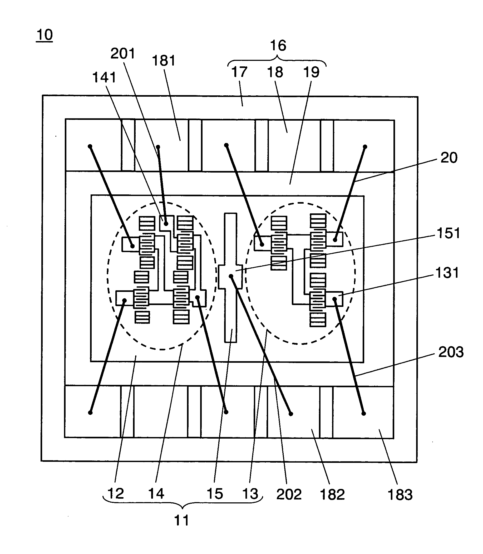
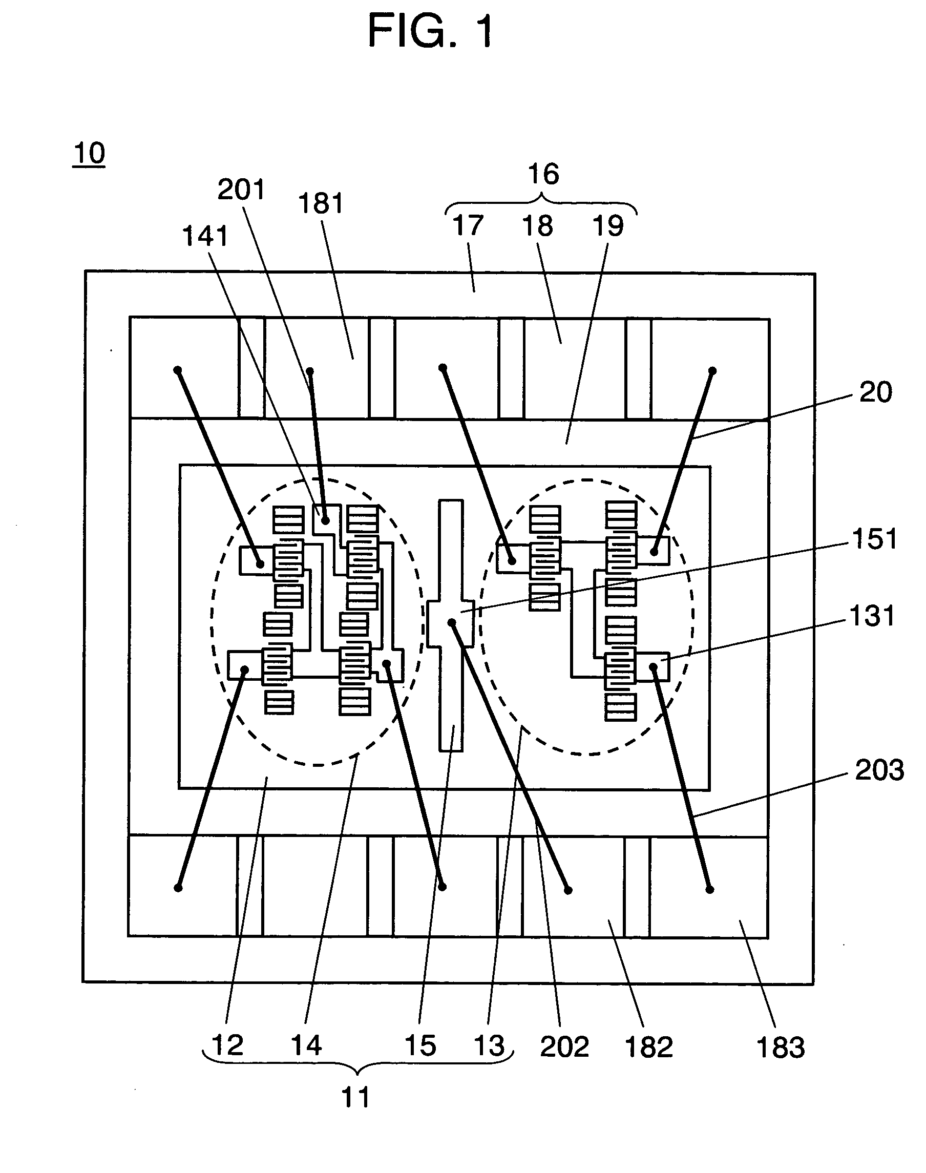
[0044]FIG. 1 is a top view showing an inside structure by removing a cover of a package in a SAW duplexer according to a first embodiment of the invention.
[0045] SAW duplexer 10 includes SAW element 11, package 16 to which SAW element 11 is fixed by bonding, wire leads 20 which connect electrode terminal patterns of SAW element 11 to terminal portions 18 of package 16 and a cover not shown.
[0046] As SAW element 11, piezoelectric substrate 12 having piezoelectricity such as a lithium tantalate (LiTaO3) single crystal substrate, a lithium niobate (LiNbO3) single crystal substrate, and a crystal substrate is used. An electrode thin film mainly including aluminum (Al) is formed on a surface of piezoelectric substrate 12 and a prescribed pattern shape is formed by performing a photolithography process and an etching process. SAW element 11 shown in FIG. 1 includes transmission filter 13 as a first surface acoustic wave filter structure, reception filter 14 as a second surface acoustic ...
second embodiment
[0063]FIG. 5 is a top view showing a structure of SAW duplexer 45 according to a second embodiment of the invention.
[0064] SAW duplexer 45 of the embodiment differs from SAW duplexer 10 of the first embodiment in the following structure.
[0065] First, shield electrode 44 is formed to be long so as to almost segment transmission filter 13 as a first surface acoustic wave filter structure and reception filter 14 as a second surface acoustic wave filter structure. In the embodiment, shield electrode 44 is formed to be longer than the length of transmission filter 13 and the reception filter.
[0066] Secondly, wire lead 206 for signals which connects transmission-side signal line terminal pattern 132 of transmission filter 13 to signal terminal 185 of package 16 is disposed so as to pass above shield electrode 44.
[0067] Thirdly, shield electrode 44 is connected to two points of earth terminals 181, 184 of package 16 by earth wire leads 204, 205, which are disposed so as to sandwich sig...
third embodiment
[0076]FIG. 8 is a top view showing a structure of SAW duplexer 60 according to a third embodiment of the invention. SAW duplexer 60 of the embodiment includes SAW element 55, package 56 to which SAW element 55 is fixed by bonding, wire leads 20 which connect electrode patterns of SAW element 55 to terminal portions 58 of package 56 and a cover not shown.
[0077] As SAW element 55, piezoelectric substrate 51 having piezoelectricity such as a lithium tantalate (LiTaO3) single crystal substrate, a lithium niobate (LiNbO3) single crystal substrate, and a crystal substrate is used. An electrode thin film mainly including aluminum (Al) is formed on a surface of piezoelectric 51 and a prescribed pattern shape is formed by performing a photolithography process and an etching process. SAW element 55 includes transmission filter 52 as a first surface acoustic wave filter structure, reception filter 53 as a second surface acoustic wave filter structure and shield electrode 54 having a grating s...
PUM
 Abstract
Description
Claims
Application Information
 - R&D
- Intellectual Property
- Life Sciences
- Materials
- Tech Scout
- Unparalleled Data Quality
- Higher Quality Content
- 60% Fewer Hallucinations
Browse by: Latest US Patents, China's latest patents, Technical Efficacy Thesaurus, Application Domain, Technology Topic, Popular Technical Reports.
© 2025 PatSnap. All rights reserved.Legal|Privacy policy|Modern Slavery Act Transparency Statement|Sitemap|About US| Contact US: help@patsnap.com


