Ink jet head, control method therefor, and ink jet recording apparatus

a control method and ink jet technology, applied in other printing apparatus, printing, etc., can solve the problems of inability to effectively prevent electric field interference inability to secure a sufficient width of shield electrodes between adjacent ejection ports, and inability to perform precise recording, etc., to prevent delay of ink ejection, improve image quality, and improve ink ejection properties

Inactive Publication Date: 2006-03-16
FUJIFILM CORP +1
View PDF3 Cites 3 Cited by
  • Summary
  • Abstract
  • Description
  • Claims
  • Application Information

AI Technical Summary

Benefits of technology

[0027] With the ink jet head control method according to the first aspect of the present invention, the AC bias voltage having the same frequency as the drive voltages applied to the ejection electrodes is controlled to be applied to the guard electrode so that the ink is easy to eject, at the time of ejection of the ink, and the ink is hard to eject at the time of non-ejection of the ink. Therefore, it becomes possible to prevent delay of the ejection of the ink and improve the ink ejection property. The ink ejection property as used here refers to a property with which a desired amount of an ink droplet is completely ejected before the completion of the ink ejecting operation. Also, it is possible to adjust the ink ejection delay and the ink ejection property independently of each other by controlling the AC bias voltage, so it becomes possible to improve image quality. Further, it becomes possible to control the ejection and non-ejection of the ink with reliability even when the voltage value of the drive voltages applied to the ejection electrodes is reduced from that in a conventional case.
[0028] Moreover, when the first voltage is set to a positive voltage and the second voltage is set to a negative voltage, the positive voltage and the negative voltage are alternately applied to the ejection electrodes, so it becomes possible to concentrate the ink by causing the colorant particles in the ink to aggregate near the surface of the ink at each of the ejection ports by means of electric fields generated between the guard electrode and the ejection electrodes when the drive voltages are applied to the ejection electrodes. Also, when the drive voltages are not applied to the ejection electrodes, the ink meniscuses at the ejection ports are pressed by electric fields generated between the guard electrode and the ejection electrodes in a direction opposite to the electric fields described above and the ink is made hard to eject, which makes it possible to prevent unnecessary spills of the ink from the ejection ports while maintaining the concentratability of the ink at the ejection ports.
[0029] Further, with the ink jet head according to the second aspect of the present invention and

Problems solved by technology

Therefore, when the ejection ports are disposed at a high density, electric field interference occurs between adjacent ejection ports and variations occur to the size of ejected ink droplets and to the flying direction of the ink droplets, which leads to a problem in that it is impossible to perform precise recording.
In the ink jet recording apparatus disclosed in JP 2000-25233 A, however, the ejection electrodes and the shield electrode are provided on the same surface, so it is impossible to shield electric lines of force generated from end portions on an outer peripheral side of the ejection electrodes with the shield electrode, which leads to a problem in that it is impossible to effectively prevent electric field interference between adjacent ejection ports.
As in the case disclosed in JP 2000-25233 A in which the shield electrode and the ejection electrodes are provided on the same

Method used


Image

  • Ink jet head, control method therefor, and ink jet recording apparatus
  • Ink jet head, control method therefor, and ink jet recording apparatus
  • Ink jet head, control method therefor, and ink jet recording apparatus

Examples


Embodiment Construction

[0042] Hereinafter, the ink jet head, the control method for the ink jet head, and the ink jet recording apparatus according to the present invention will be described in detail based on preferred embodiments illustrated in the accompanying drawings.

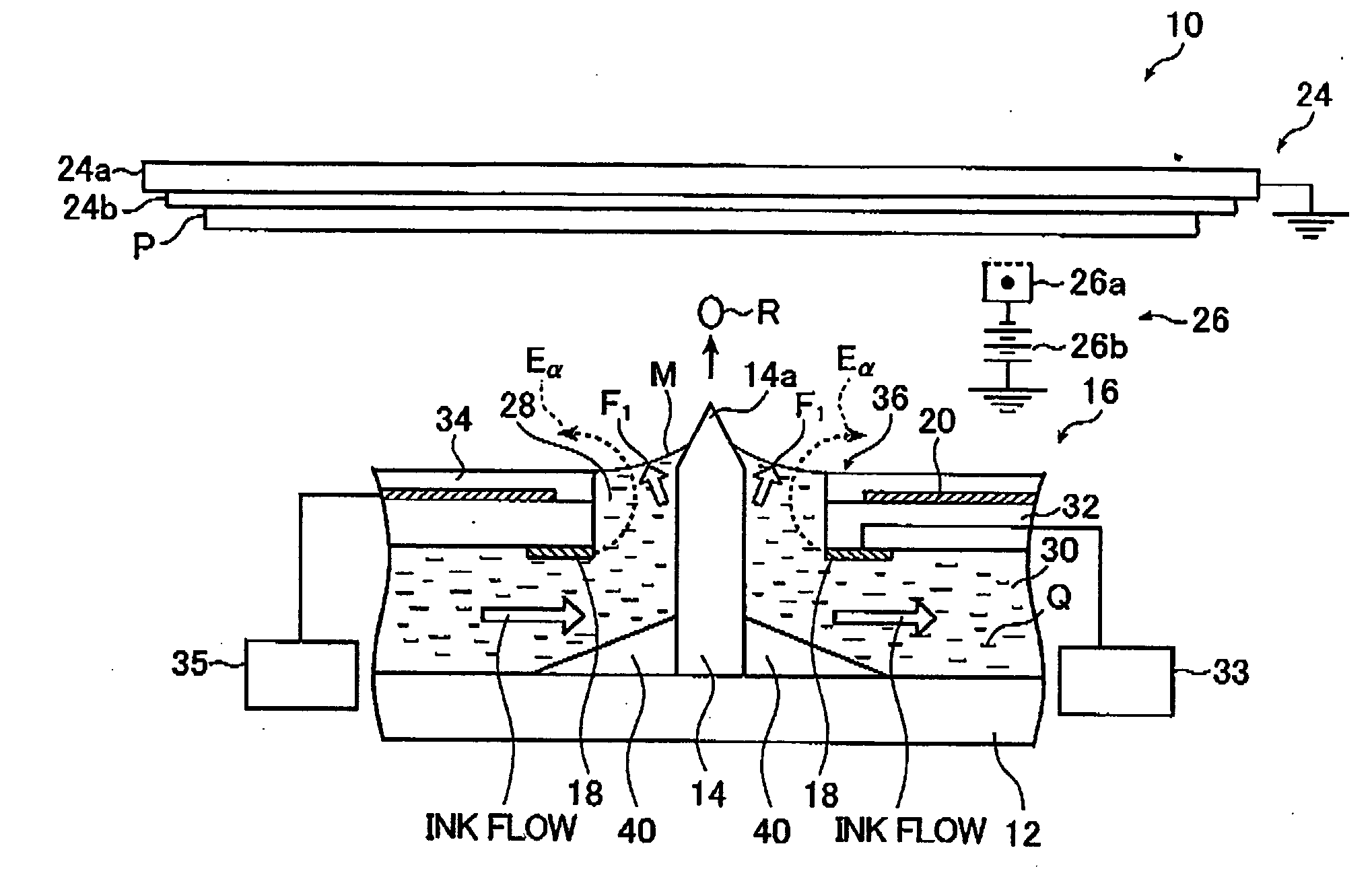
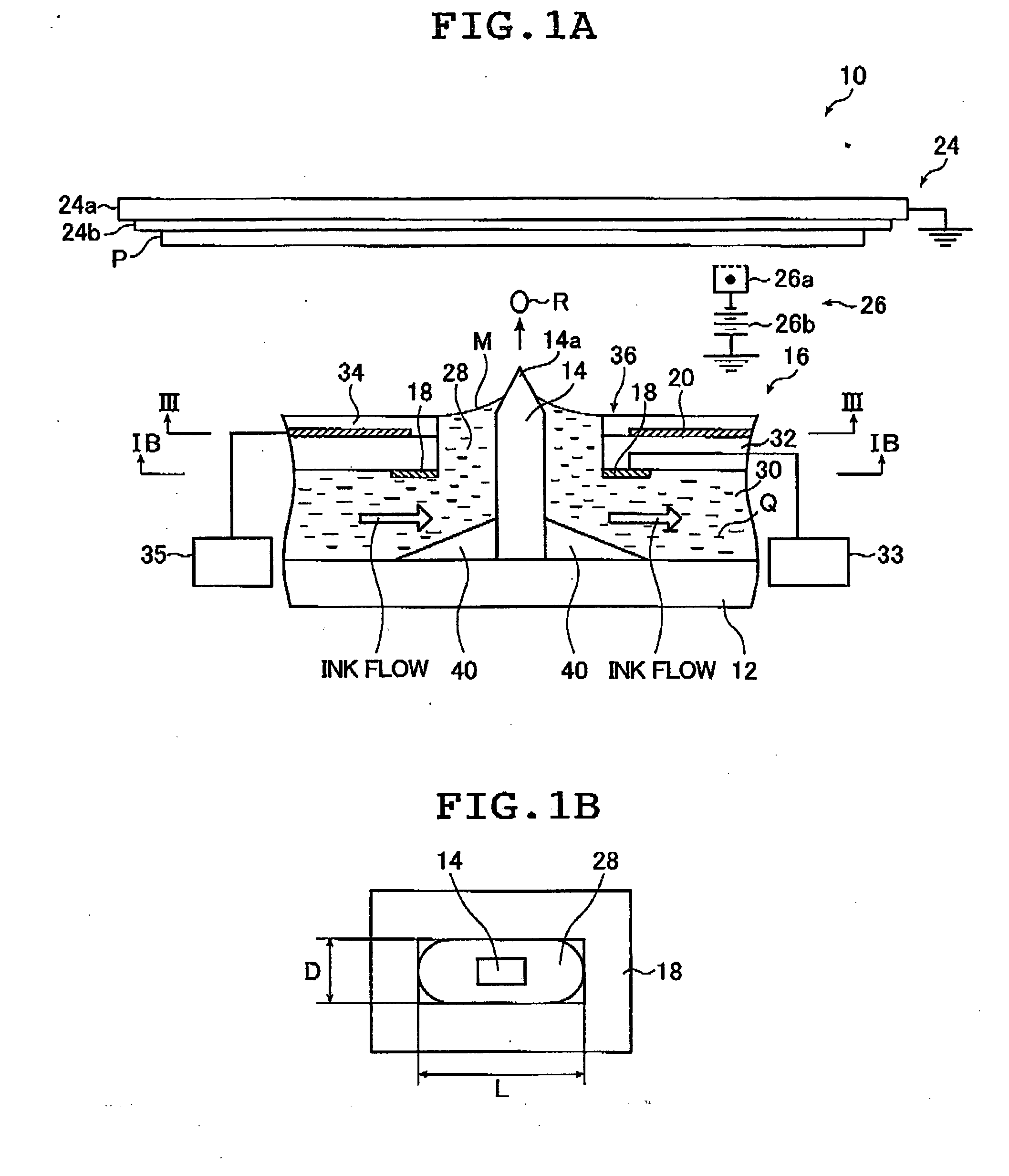
[0043]FIG. 1A schematically shows a cross section of an outlined construction of the ink jet head according to the present invention and FIG. 1B is a cross-sectional view taken along line IB-IB in FIG. 1A. As shown in FIG. 1A, an ink jet head 10 includes a head substrate 12, ink guides 14, and an ejection port substrate 16 in which ejection ports 28 are formed. For the ejection port substrate 16, an ejection electrode 18 is disposed so that it surrounds the ejection port 28. At positions facing a surface on an ink ejection side (upper surface in FIG. 1A) of the ink jet head 10, a counter electrode 24 supporting a recording medium P and a charge unit 26 for charging the recording medium P are disposed.

[0044] Also, the head substrate 12 ...


PUM


Abstract

The present invention provides a control method for controlling an ink jet head. The inkjet head includes an ejection port substrate having ejection ports for ejection of the droplets, ejection electrodes respectively being located in a position corresponding to each of the ejection ports, and a guard electrode formed in the ejection port substrate. The control method includes the steps of: applying a drive voltage to each of the ejection electrodes in accordance with a drawing signal; and applying an AC bias voltage to the guard electrode, the AC bias voltage having the same frequency as the drive voltage applied to each of the ejection electrodes and alternately repeating a first voltage and a second voltage being lower than the first voltage.

Description

[0001] The entire contents of literatures cited in this specification are incorporated herein by reference. BACKGROUND OF THE INVENTION [0002] The present invention relates to an ink jet head, a control method for the ink jet head, and an ink jet recording apparatus with which an image is formed on a recording medium by ejecting ink toward the recording medium. More specifically, the present invention relates to an ink jet head, a control method for the ink jet head, and an ink jet recording apparatus with which ink containing charged fine particles are ejected through the ink jet head by utilizing electrostatic forces. [0003] An electrostatic ink jet recording system is known in which ink is ejected toward a recording medium by utilizing electrostatic forces. In the electrostatic ink jet recording system, ink containing a charged fine particle component is used and ink droplets are ejected from ejection ports for ejection of the ink toward a recording medium by exerting electrostat...

Claims


Application Information

Patent Timeline
IPC IPC(8): B41J29/38
CPCB41J2/06
Inventor NAKAZAWA, YUSUKEFURUKAWA, KOJI
Owner FUJIFILM CORP
Why Eureka
Try Eureka