Image capturing apparatus, and method of setting flash synchronization speed

Inactive Publication Date: 2006-03-16
KONICA MINOLTA PHOTO IMAGING
View PDF3 Cites 18 Cited by
  • Summary
  • Abstract
  • Description
  • Claims
  • Application Information

AI Technical Summary

Benefits of technology

[0026] It is therefore an object of the present invention to provide an image capturing technique capable of extend

Problems solved by technology

Accordingly, light reflected from the subject is partly blocked by the rear curtain during flash emission, causing part of the exposure area to be insufficiently exposed.
As described, setting the shutter speed high results in a nonuniform amount of exposure on the exposure area.
In the image capturing apparatus employing the above-described camera-shake compensation technology, however, a predetermined flash synchronization speed limits a settable range of exposure conditions.
In other words, setting of more preferable shooting c

Method used


Image

  • Image capturing apparatus, and method of setting flash synchronization speed
  • Image capturing apparatus, and method of setting flash synchronization speed
  • Image capturing apparatus, and method of setting flash synchronization speed

Examples


first preferred embodiment

Outline of Image Capturing Apparatus

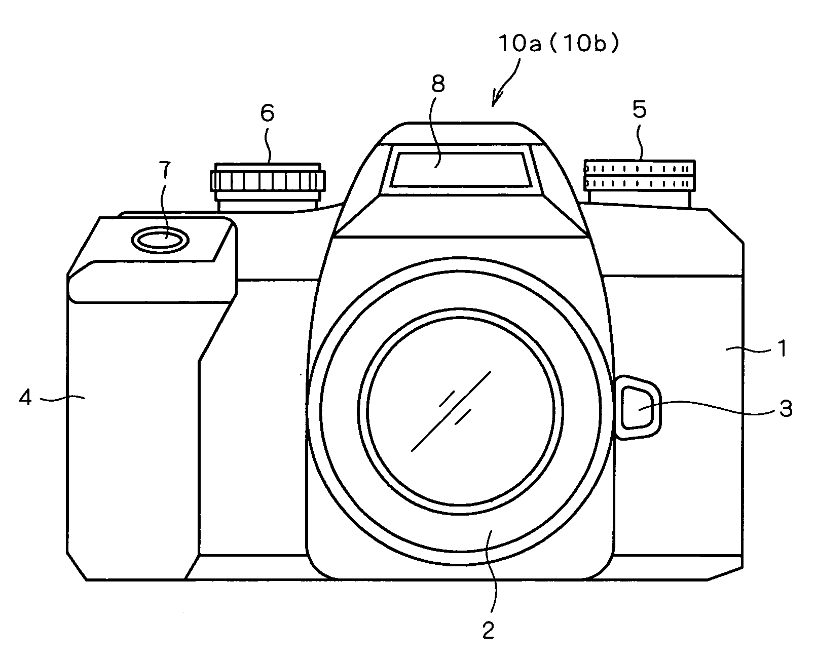
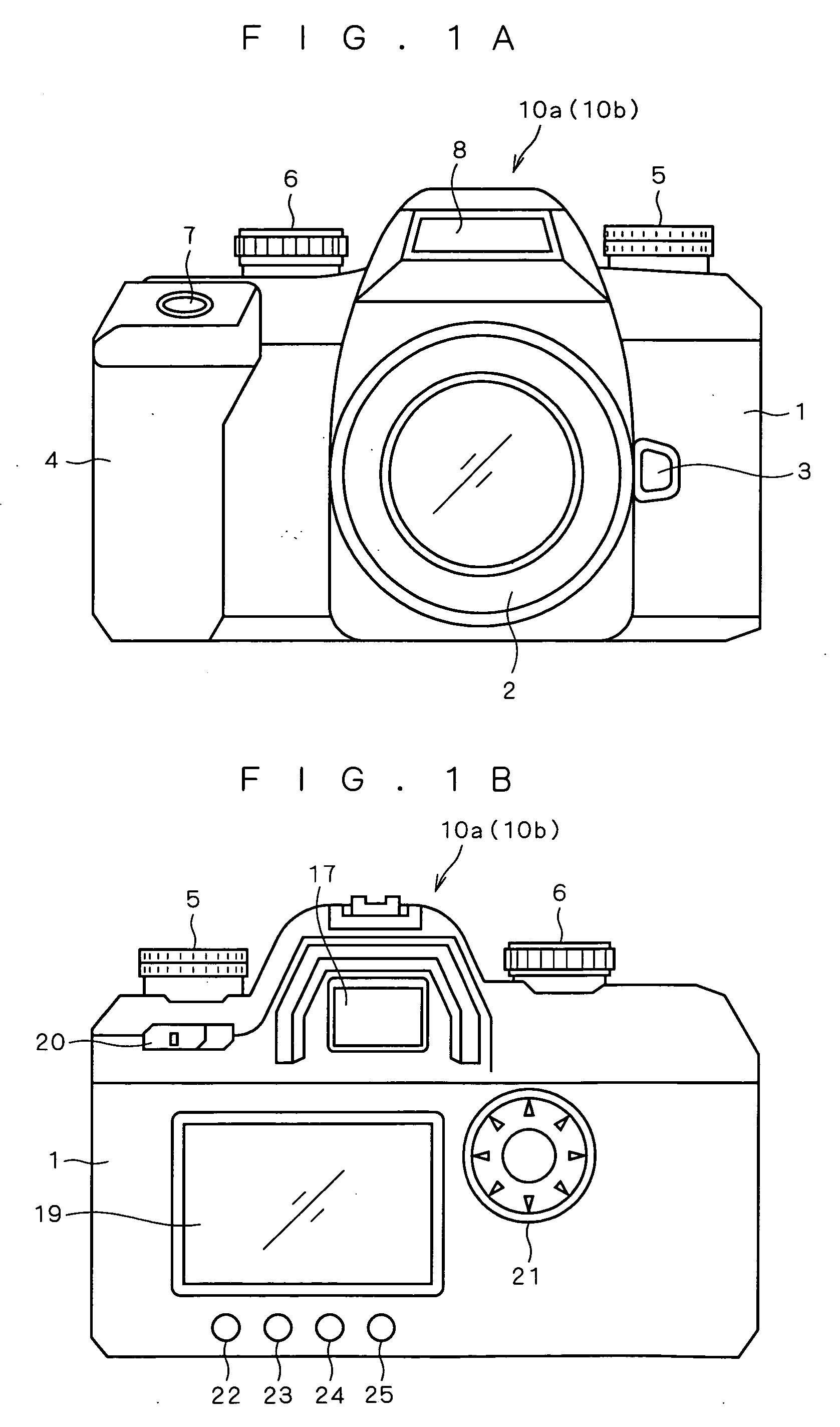
[0041]FIGS. 1A and 1B each illustrate an external construction of an image capturing apparatus 10a according to a first preferred embodiment of the present invention. FIG. 1A is an external front view, and FIG. 1B is an external rear view.

[0042] As shown in FIG. 1A, the image capturing apparatus 10a according to the present embodiment is constructed from a single lens reflex digital camera including a camera body 1 and an interchangeable lens device (corresponding to a taking lens device) 2 detachably attached almost at the center of the front face of the camera body 1.

[0043] In FIG. 1A, the camera body 1 is provided with a mounting part (not shown) near almost the center of its front face to which the interchangeable lens device 2 is mounted, an attaching / detaching button 3 near the mounting part for attaching / detaching the interchangeable lens device 2, a grip 4 on the left side on its front face to be held by a user, a control-value setting...

second preferred embodiment

[0124] The above-described image capturing apparatus 10a according to the first preferred embodiment increases the flash synchronization speed by advancing as much as possible the timing of driving the rear curtain PB in the camera-shake compensation OFF mode. An image capturing apparatus 10b according to a second preferred embodiment is capable of increasing the flash synchronization speed further by advancing the timing of start of flash emission from the built-in flash 8 with respect to the driving of the shutter 112. The image capturing apparatus 10b according to the present embodiment and the image capturing apparatus 10a according to the first preferred embodiment differ from each other only in the method of increasing the flash synchronization speed and the use of electrical contacts for starting flash emission from the built-in flash 8. Other configuration and the like are similar to each other.

[0125] Hereinafter, the same components are indicated by the same reference char...


PUM


Abstract

An image capturing technique capable of extending a settable range of exposure conditions and achieving appropriate image capturing in accordance with a subject is provided. In response to an operation of a mode setting dial included in an operation unit, a selection is made between a camera-shake compensation ON mode for achieving camera-shake compensation and a camera-shake compensation OFF mode for not achieving camera-shake compensation, under the control of an overall control section. Then, a flash synchronization speed is set higher in the camera-shake compensation ON mode than in the camera-shake compensation OFF mode.

Description

[0001] This application is based on application No. 2004-266799 filed in Japan, the contents of which are hereby incorporated by reference. BACKGROUND OF THE INVENTION [0002] 1. Field of the Invention [0003] The present invention relates to an image capturing apparatus. [0004] 2. Description of the Background Art [0005] An image capturing apparatus such as a single lens reflex camera employs a mechanism such as a focal plane shutter for controlling exposure time. [0006] In the case of flash shooting with an image capturing apparatus employing such a mechanical shutter, the lowest limit of a shutter speed (called a “flash synchronization speed”) is to be determined depending on an operating speed of the mechanical shutter in order to make uniform exposure on the whole of an area to be exposed (hereinafter referred to as an “exposure area”) in which an imaging device, a film and the like are placed. In other words, the flash must be fired with the whole exposure area being uniformly i...

Claims


Application Information

Patent Timeline
IPC IPC(8): H04N5/228G03B5/00G03B7/16G03B15/03G03B15/05H04N5/232H04N5/238
CPCH04N5/23245H04N5/2354H04N5/2329H04N5/23248H04N23/667H04N23/68H04N23/689H04N23/74
Inventor KAWABE, KOUTARO
Owner KONICA MINOLTA PHOTO IMAGING
Why Eureka
Try Eureka