Wire grid polarizer and manufacturing method thereof

a wire grid polarizer and manufacturing method technology, applied in the direction of polarizing elements, instruments, applications, etc., can solve the problems of difficult to manufacture wire grid polarizers with a shorter period of wire grid, plain glass does not transmit 100% of incident light, etc., to achieve easy and repeated manufacturing and excellent polarizing performance

Inactive Publication Date: 2006-03-16
LG ELECTRONICS INC
View PDF19 Cites 44 Cited by
  • Summary
  • Abstract
  • Description
  • Claims
  • Application Information

AI Technical Summary

Benefits of technology

[0033] Accordingly, one object of the present invention is to solve the foregoing problems by providing a wire grid polarizer for visible light and a manufacturing method thereof using embossing technique, whereby wire grid polarizers can be more easily and repeatedly manufactured.
[0034] Another object of the present invention is to provide a wire grid polarizer having excellent polarizing performance at the R, G, and B wavelengths in the visible spectrum

Problems solved by technology

In practice, however, reflective metals used as mirrors absorb some fraction of the incident light and reflect only 90-95%, and plain glass does not transmit 100% of the incident light because of surface reflections.
So far, it has been very difficult to manufacture wire grid polarizers with a shorter period of the wire grid, so wire grid polarizers were developed only for use in the infrared or microwave regions.

Method used


Image

  • Wire grid polarizer and manufacturing method thereof
  • Wire grid polarizer and manufacturing method thereof
  • Wire grid polarizer and manufacturing method thereof

Examples


first embodiment

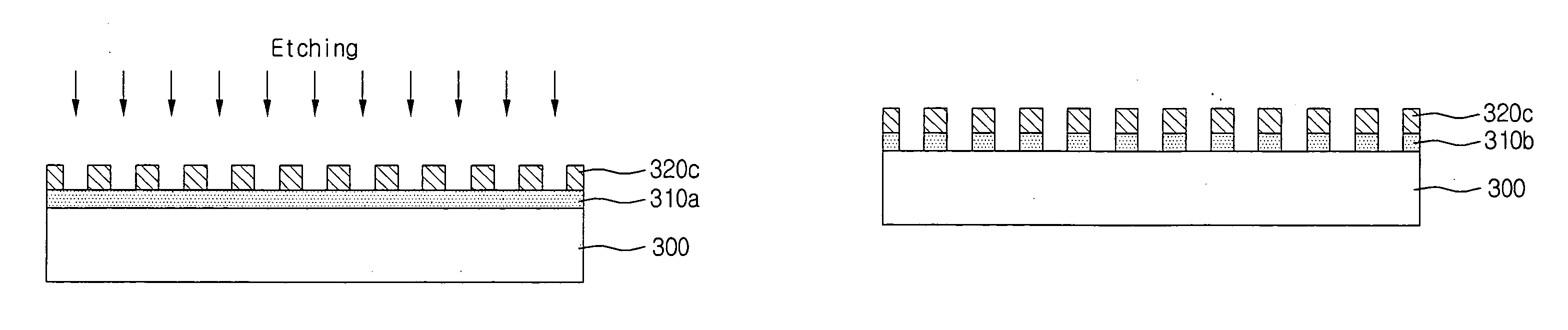
[0065]FIGS. 4A to 4H illustrate a sequence of a manufacturing process of a wire grid polarizer, according to the present invention.

[0066] As described before, the wire grid polarizer is manufactured by using the pre-made mold. To this end, a transparent glass substrate 300 with both surfaces polished is first prepared (refer to FIG. 4A).

[0067] Then, as shown in FIG. 4B, a thin metal foil 310a is deposited on the glass substrate 300.

[0068] The metal foil 310a can be made from Al, Ag, or Cr.

[0069] Later, the metal foil 310a is coated with a polymer 320a, as shown in FIG. 4C

[0070] The polymer 320a is pressed by the mold 330, and as a result, the pattern from the mold is printed onto the polymer 320a.

[0071] Here, if the polymer 320a is a thermosetting material, a metal mold is employed, and if the polymer 320a is a UV cure material, a transparent polymer mold is employed.

[0072] In the former case where the polymer 320a is a thermosetting material, the hot embossing technique is use...

second embodiment

[0083]FIGS. 5A to 5G illustrate a sequence of a manufacturing process of a wire grid polarizer, according to the present invention.

[0084] As explained before, the wire grid polarizer is manufactured by using the pre-made mold. To this end, a transparent glass substrate with both surfaces polished is first prepared (refer to FIG. 5A).

[0085] Later, as shown in FIG. 5B, the glass substrate 400 is coated with a polymer 410a, and the mold 430 is prepared.

[0086] Then, the polymer 410a is pressed by the mold 430, and as a result, the pattern from the mold 430 is printed onto the polymer 410b, as shown in FIG. 5G

[0087] The pattern printed onto the polymer 410b is opposite to the pattern from the mold 430.

[0088] As shown in FIG. 5D, by applying heat or irradiating ultraviolet light onto the mold 430, the polymer 410b is cured or solidified

[0089] In case of using the hot embossing technique, the mold 430 has to be separated from the polymer 410b after the temperature of the substrate 400 ...


PUM

PropertyMeasurementUnit
wavelengthsaaaaaaaaaa
widthaaaaaaaaaa
photosensitiveaaaaaaaaaa

Abstract

A manufacturing method of a wire grid polarizer includes the steps of: preparing a mold; sequentially forming a metal foil and a polymer on a substrate; molding a polymer by using the mold; etching the metal foil by using the molded polymer, and forming a wire grid pattern; and removing the polymer.

Description

BACKGROUND OF THE INVENTION [0001] 1. Field of the Invention [0002] The present invention relates in, general to a wire grid polarizer and a manufacturing method thereof, more particularly, to a wire grid polarizer for visible light and a manufacturing method thereof. [0003] 2. Discussion of the Background Art [0004] The use of an array of parallel conducting wires to polarize specific light of radio waves dates back more than 100 years. [0005] The array of parallel conducting wires is generally called a wire grid. The wire grid, formed on a transparent substrate, is also used as a polarizer for the infrared portion of the electromagnetic spectrum. [0006] The key factor that determines the performance of a wire grid polarizer is the relationship between the wire-to-wire spacing, namely period of the parallel grid elements and the wavelength of the incident light. [0007] If the period of the wire grid is longer than the wavelength of the incident light, the wire grid functions as a d...

Claims


Application Information

Patent Timeline
Patent Type & Authority Applications(United States)
IPC IPC(8): G02B5/30
CPCG02B5/3058
Inventor AHN, SEH WONLEE, KI DONGLEE, SUNG EUNYOON, SANG SOOKIM, JIN SUNGPARK, JOO DO
Owner LG ELECTRONICS INC
Why Eureka
Try Eureka