Ring binder mechanism

Inactive Publication Date: 2006-03-16
ESSELTE LEITZ GMBH & CO KG
View PDF6 Cites 74 Cited by
  • Summary
  • Abstract
  • Description
  • Claims
  • Application Information

AI Technical Summary

Benefits of technology

[0012] A ring binder mechanism with four rings can accordingly be equipped with four locking elements, wherein the locking elements are mounted pivotably upon one of the two carrier rails and each locking element can be associated with a locking spring in the form of a leg spring. The locking elements can be provided with wedge-shaped locking surf

Problems solved by technology

The use of more than two locking elements is desirable, for example, in mec

Method used


Image

  • Ring binder mechanism
  • Ring binder mechanism
  • Ring binder mechanism

Examples


Embodiment Construction

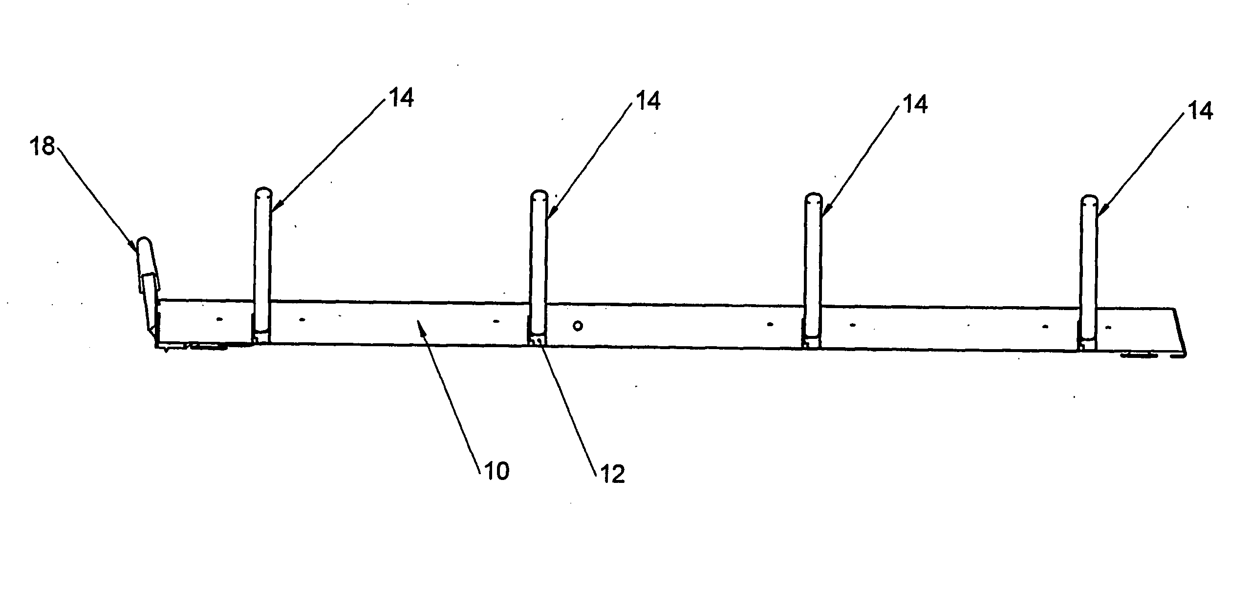
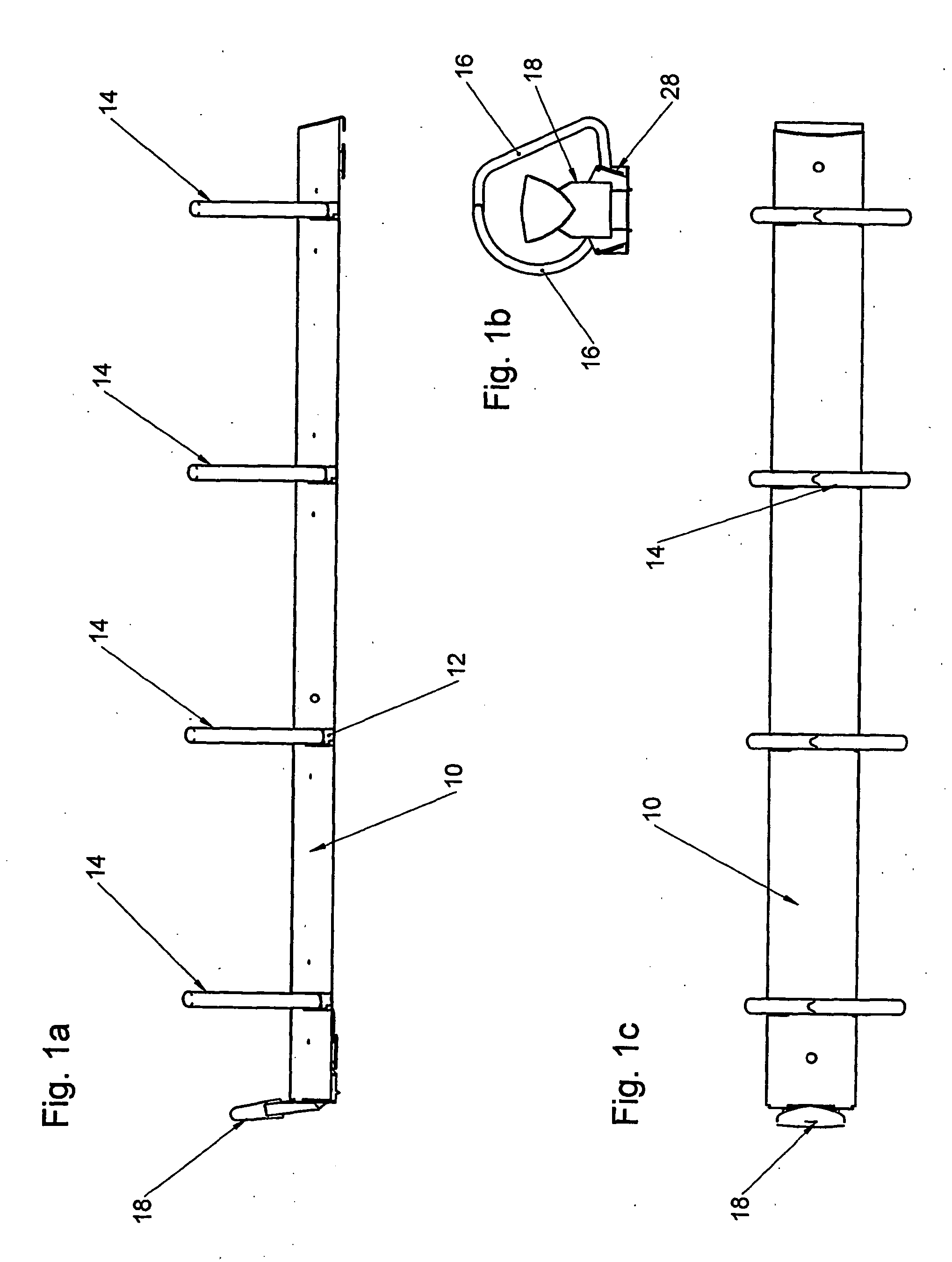
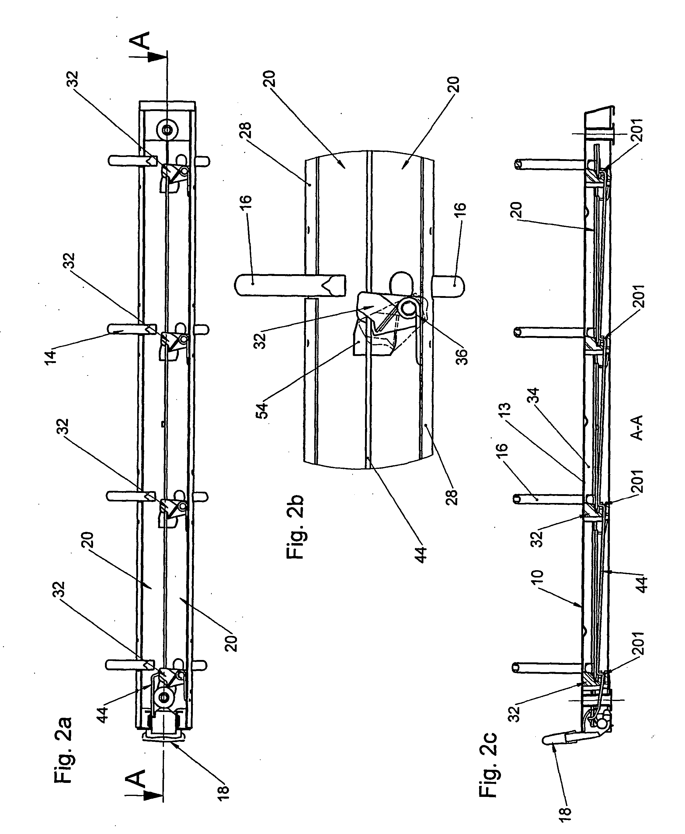
[0027] The binder ring mechanisms represented in the drawings are above all intended for receiving loose-leaf, holed sheets, for example, writing material or printed products.

[0028] The binder ring mechanism is comprised essentially of a housing, multiple half-rings 16 provided longitudinally spaced from each other and extending through openings 12 in the housing wall 13 and pairwise forming a ring 14 with complementary half-rings, as well as an operating lever 18 for opening and closing the rings. Each of the half-rings 16 of one of the rings 14 is rigidly secured to one of the two carrier rails 20, which on their inward edges—the longitudinal edges facing each other—lie against each other thereby forming a linkage axis 22, and which with their outer edges—the longitudinal edges 24 facing away from each other—engage in inward facing mounting grooves 26 stamped into the housing flanks 28. The carrier rails 20 are introduced into the housing in such a manner, that they can assume tw...


PUM


Abstract

The invention relates to a ring binder mechanism for housing perforated documents. The ring binder mechanism comprises a housing (10) with spring elastically flexible housing flanks (28). Two carrier rails (20) are arranged within the housing (10), which may be pivoted towards each other by the spring action of the housing flanks (28) in the manner of an elbow joint in the region of the longitudinal edges thereof which face each other. At least two half rings (16), which pair-wise form a ring (14), are rigidly connected to the support rails (20) at defined longitudinal separations from each other. At least two locking elements (32), operated by means of an actuating element (18) and a tie rod (44), are further provided, which engage in a free space (34), formed between the carrier rails (20) and a housing wall (13), in the locked position, with locking of the pivoting movement of the carrier rails (20) and which release the pivoting path about the joint axis (22) in the opened state, whereby the locking elements (32) are pre-tensioned in the closing direction by the action of a closing spring (36). According to the invention, only one single tie rod (44) is provided, the tie rod comprising several dogs (201), each of which is provided for cooperating with one of the locking elements (32).

Description

BACKGROUND OF THE INVENTION [0001] 1. Field of the Invention [0002] The invention concerns a ring binder mechanism with a housing having a C-shaped or U-shaped cross-section, with elastic mounting flanks which can be bent open for receiving two carrier rails, of which the inward facing longitudinal edges lie against each other forming a linkage axis, and of which the outward facing longitudinal edges engage in mounting grooves of the mounting flanks, and with at least two half-rings rigidly connected with the carrier rail in a defined longitudinal separation from each other, extending through openings in a housing wall and pairwise forming themselves into a ring, wherein the carrier rails, taking along the half rings, are limitedly pivotable relative to each other about the longitudinal pivot axis between an open position and a closed position while overcoming the spring force produced by the bending open of the mounting flanks, and wherein at least two locking elements are provided...

Claims


Application Information

Patent Timeline
IPC IPC(8): B42F13/20B42F13/26
CPCB42F13/26
Inventor HORN, HANS JOHANN
Owner ESSELTE LEITZ GMBH & CO KG
Why Eureka
Try Eureka