System and method for specifying functional and non-functional requirements for a project

a technology of functional requirements and project requirements, applied in the field of model requirements, can solve the problems of not being communicated to the architectural team, not being able to achieve the effect of reducing the number of requirements, tracing, and reading difficulties, and achieving the effect of simplifying the reuse of requirements

Inactive Publication Date: 2006-03-16
SIEMENS AG
View PDF7 Cites 37 Cited by
  • Summary
  • Abstract
  • Description
  • Claims
  • Application Information

AI Technical Summary

Problems solved by technology

If the resultant set of requirements is large, traceability, readability and verification can be difficult.
There are difficulties inherent in the above approach.
In addition, because different subject matter experts are used on different teams, they often do not review each other's work.
This means that (1) functional requirements discovered during architectural sessions may not get communicated to the requirements team; and (2) non-functional requirements discovered during modeling or use case writing or reviews may not get communicated to the architectural team.
When the requirements are elicited using different teams, tools, and processes, tracing between requirements can be problematic.
This approach breaks down with large databases as it becomes increasingly difficult to identify all the necessary links.
Hazard analysis also presents additional challenges to the requirements analyst.
An example would be the potential hazard to a person receiving an excessive dose of X-rays when getting a dental checkup.
The embedded software that controls the X-ray machine has an identifiable hazard.
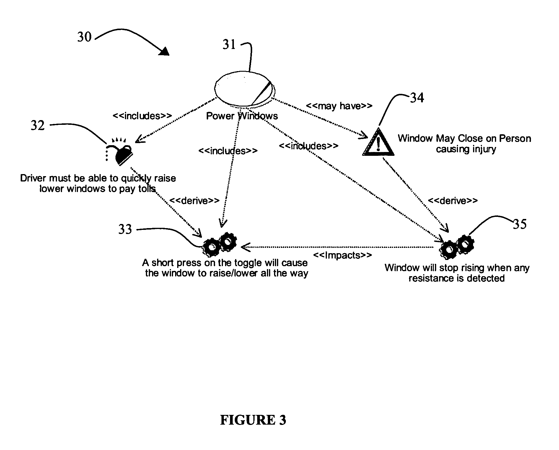
The resultant mitigation strategy may result in the generation of more functional and non-functional requirements that are difficult to back trace to the hazard from which they derive.
Another issue associated with diverse, simultaneous efforts is that of synchronizing requirements with UML use case diagrams.
Nevertheless, post-analysis, connecting requirements back to their associated use-cases can be a time-consuming task.
As the project moves forward, the artifacts get larger, and the effort to trace requirements back to their origins becomes increasingly difficult.

Method used


Image

  • System and method for specifying functional and non-functional requirements for a project
  • System and method for specifying functional and non-functional requirements for a project
  • System and method for specifying functional and non-functional requirements for a project

Examples


Embodiment Construction

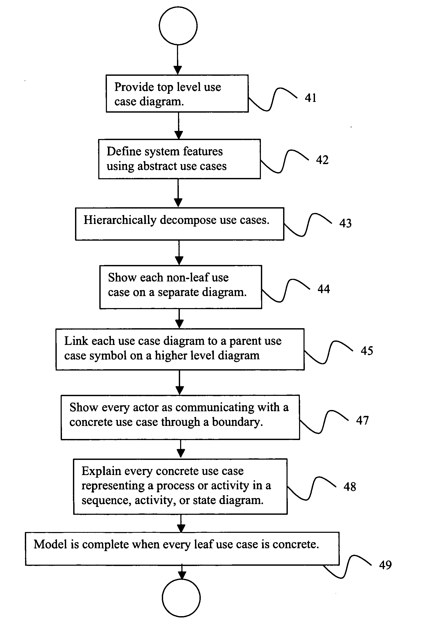
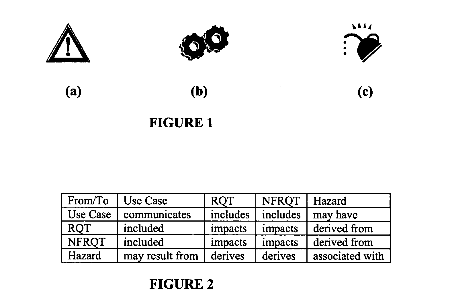
[0035] Exemplary embodiments of the invention as described herein generally include systems and methods for extending UML to support the integration of hazard and requirements analysis and the binding of resultant exposed requirements to their respective use cases, with enabling tool support.

[0036] The Unified Modeling Language (UML) is a standard language for specifying, visualizing, constructing and documenting the artifacts of software systems, as well as for business modeling and other non-software systems. The UML represents a collection of best engineering practices that have proven successful in the modeling of large and complex systems. UML forms an integral part of object oriented software development and three software development process. UML uses mostly graphical notations to express the design of software systems. Using UML helps project teams communicate, explore potential designs, and validate the architectural design of a software system.

[0037] There are currently ...


PUM


Abstract

A method for modeling requirements of a product includes defining an abstract use case for each feature of said product; hierarchically decomposing each abstract use case until concrete use cases are specified for each feature; depicting every actor who would use said product as communicating with a concrete use case through a boundary; and programmatically extracting requirements from said use case diagram. Programmatically extracting requirements further includes converting use case diagrams into directed acyclic graphs, wherein each use case corresponds to a node of a graph, and each relationship between a pair of use cases is represented by a directed edge between the corresponding pair of nodes in said graph, wherein a directed edge points from a parent node to a child node, converting said directed acyclic graph into a tree, and searching said tree to extract said requirements.

Description

CROSS REFERENCE TO RELATED UNITED STATES APPLICATIONS [0001] This application claims priority from “A Unified System for Defining Functional and Non-Functional Requirements”, U.S. Provisional Application No. 60 / 604,521 of Brian Berenbach, filed Aug. 26, 2004, the contents of which are incorporated herein by reference.TECHNICAL FIELD [0002] This invention is directed to modeling requirements for software systems development, and to graphical models for visualizing the relationships between product features, hazards, and requirements. DISCUSSION OF THE RELATED ART [0003] The typical process by which requirements are defined on large projects has not changed for several years. Teams of analysts and subject matter experts define functional requirements. Architects and other experts define non-functional requirements. If the resultant set of requirements is large, traceability, readability and verification can be difficult. There are difficulties inherent in the above approach. Functiona...

Claims


Application Information

Patent Timeline
Patent Type & Authority Applications(United States)
IPC IPC(8): G06F17/50
CPCG06F17/50G06Q10/06G06Q10/04G06F30/00
Inventor BERENBACH, BRIANFOSTER, HERBERT R. JR.SHERMAN, WILLIAM
Owner SIEMENS AG
Why Eureka
Try Eureka