Method and apparatus for cutting sheet metal

a technology of sheet metal and cutting tools, applied in the direction of laser beam welding equipment, gas flame welding apparatus, welding/soldering/cutting articles, etc., can solve the problems of sheet metal sliding and jerky motion, and achieve the effect of less waste and more economics

Inactive Publication Date: 2006-03-23
KOENDERS WILF
View PDF0 Cites 7 Cited by
  • Summary
  • Abstract
  • Description
  • Claims
  • Application Information

AI Technical Summary

Benefits of technology

[0006] It is the object of the present invention to provide an apparatus for cutting sheet metal pieces from a sheet metal coil more economically and with less waste than present apparatuses for cutting such pieces from a sheet metal plate.

Problems solved by technology

The inertia of the sheet metal coil can be quite substantial where the coil is large, leading to slippage and jerky motion of the sheet metal where the inertia must be overcome by the sheet metal drive.

Method used


Image

  • Method and apparatus for cutting sheet metal
  • Method and apparatus for cutting sheet metal
  • Method and apparatus for cutting sheet metal

Examples


Embodiment Construction

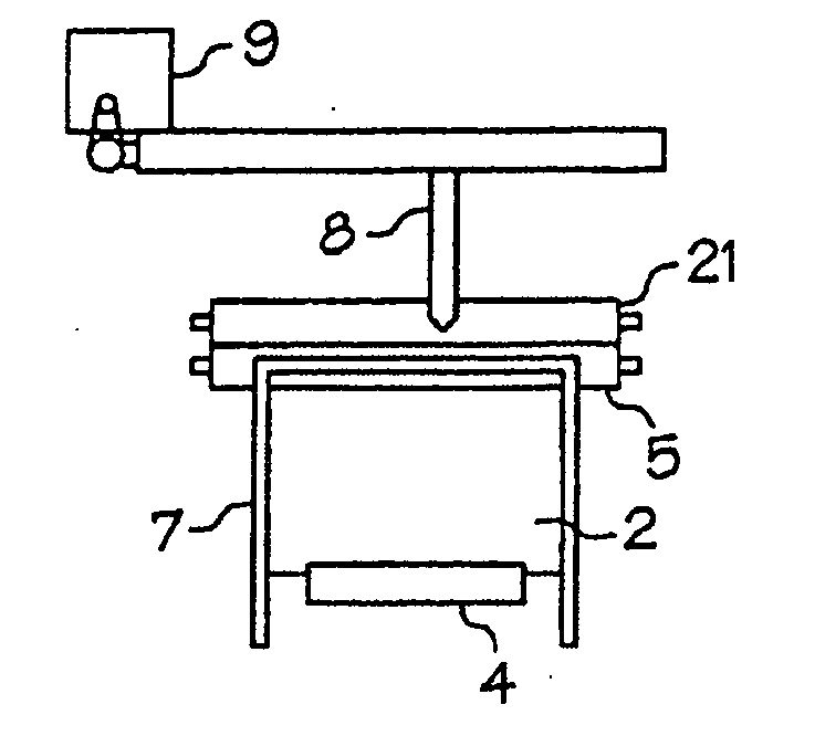
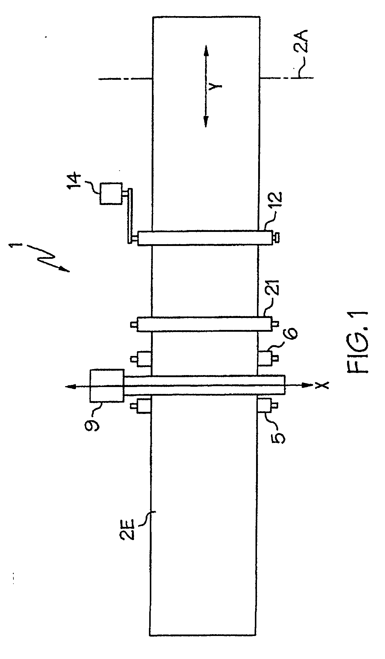
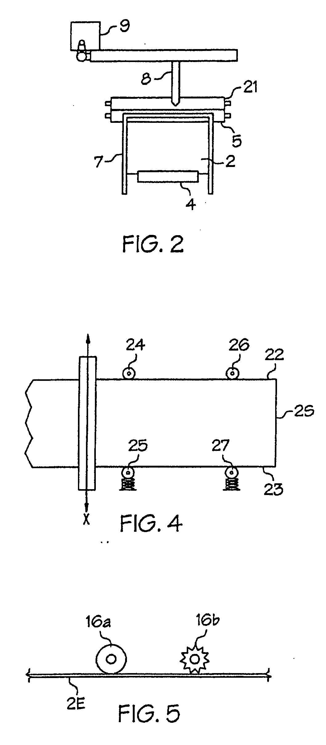
[0020]FIGS. 1-3 illustrate an apparatus 1 for cutting sheet metal pieces from a sheet metal coil 2 having a coil axis 2A. In the apparatus 1 of FIGS. 1-3 a coil support comprises coil rollers 3 and 4 which support the sheet metal coil 2 such that same may rotate about the coil axis 2A to unroll an end portion 2E. An alternate coil support is described below.

[0021] A sheet support, as illustrated comprising a pair of support rollers 5, 6, and table 7, supports the end portion 2E for cutting. Further rollers, or other supports may be substituted for the table 7, or for short pieces the table might be removed. The size and shape of the pieces being cut will dictate what support is needed for the end portion 2E.

[0022] A cutting head 8 is mounted above the support rollers 5, 6 and end portion 2E resting thereon, and is operative to cut through the end portion 2E. A cutting head drive 9 is operative to move the cutting head 8 back and forth along a first path X parallel to the coil axis...


PUM

PropertyMeasurementUnit
movementsaaaaaaaaaa
sizesaaaaaaaaaa
speedaaaaaaaaaa

Abstract

An apparatus for cutting sheet metal pieces from a sheet metal coil comprises a coil support adapted to support the sheet metal coil such that same may rotate about the coil axis to unroll an end portion of the sheet metal coil and a sheet support adapted to support the end portion for cutting. A cutting head is mounted above the end portion and is operative to cut through the end portion. A cutting head drive is operative to move the cutting head back and forth along a first path parallel to the coil axis and a sheet metal drive is operative to move the end portion forward and rearward along a second path perpendicular to the coil axis. A computer is operative to control and coordinate the sheet metal drive and the cutting head drive such that the pieces are cut from the end portion.

Description

[0001] This application is a continuation-in-part of U.S. patent application Ser. No. 10 / 032,521 METHOD AND APPARATUS FOR CUTTING SHEET METAL. This invention is in the field of metal working and in particular cutting sheet metal.BACKGROUND OF THE INVENTION [0002] Sheet metal is generally available either in plates or coils of various sizes. The user generally cuts the pieces he requires from the plate or coil. [0003] Computerized cutting tables are presently available wherein a plate of sheet metal is laid on the table, and cuts through the plate are made in an X-Y grid to obtain the required pieces. A cutting head, using oxygen / acetylene, laser, water, plasma or the like, is mounted on a carriage above the table and controlled by the computer to move in both the X and Y directions in a coordinated fashion to keep the speed of the cutting head relative to the plate substantially constant. The shape of the desired piece, or of many different pieces, is programmed into the computer an...

Claims


Application Information

Patent Timeline
Patent Type & Authority Applications(United States)
IPC IPC(8): B26D1/00B23K7/10B23K26/08B23K26/38B26F1/38B26F3/00
CPCB23K7/102B23K26/0846B26F3/004B23K2203/04B26F1/382B23K2201/16B23K2101/16B23K2103/04Y10T83/04Y10T83/8822Y10T83/896
Inventor KOENDERS, WILF
Owner KOENDERS WILF
Why Eureka
Try Eureka