
Baffle plate

a technology of baffle plate and plate body, which is applied in the direction of gearing details, machines/engines, drip or splash lubrication, etc., can solve the problems of difficult and achieve the effect of easy contact and easy design and manufacture of baffle pla

Inactive Publication Date: 2006-03-23
JATCO LTD
View PDF6 Cites 23 Cited by
  • Summary
  • Abstract
  • Description
  • Claims
  • Application Information

AI Technical Summary

Benefits of technology

[0009] It is therefore an object of the present invention to provide a baffle plate which conforms to the shape of the inner peripheral surface of a transmission case and can be easily brought into contact with the inner peripheral surface of the transmission case, making it easier to design and manufacture the baffle plate.
[0011] According to the present invention, the baffle plate is closely attached to the inner peripheral surface of the transmission case via the sealing member, and hence even in the case where the inner peripheral surface of the transmission case has a complex shape, the baffle plate can be closely attached to the inner peripheral surface of the transmission case. Therefore, the baffle plate can be easily designed and manufactured.

Problems solved by technology

However, in the case where the inner peripheral surface of the transmission case has a complex shape, it is very difficult to design and manufacture the baffle plate because the opening of the baffle plate must conform to the complex shape.

Method used


Image

  • Baffle plate
  • Baffle plate
  • Baffle plate

Examples


Embodiment Construction

[0021] The present invention will now be described in detail with reference to the accompanying drawings showing a preferred embodiment thereof.

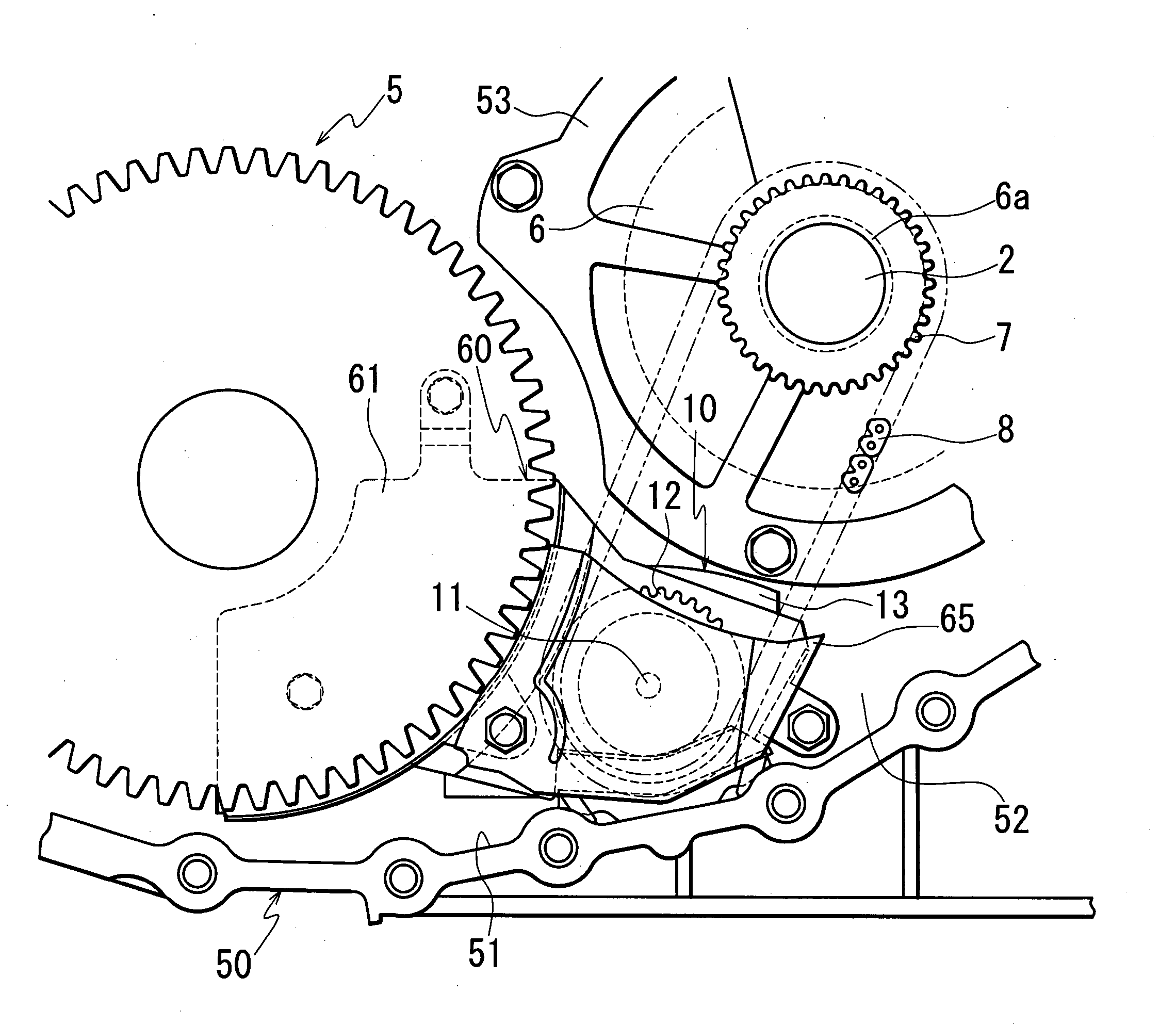
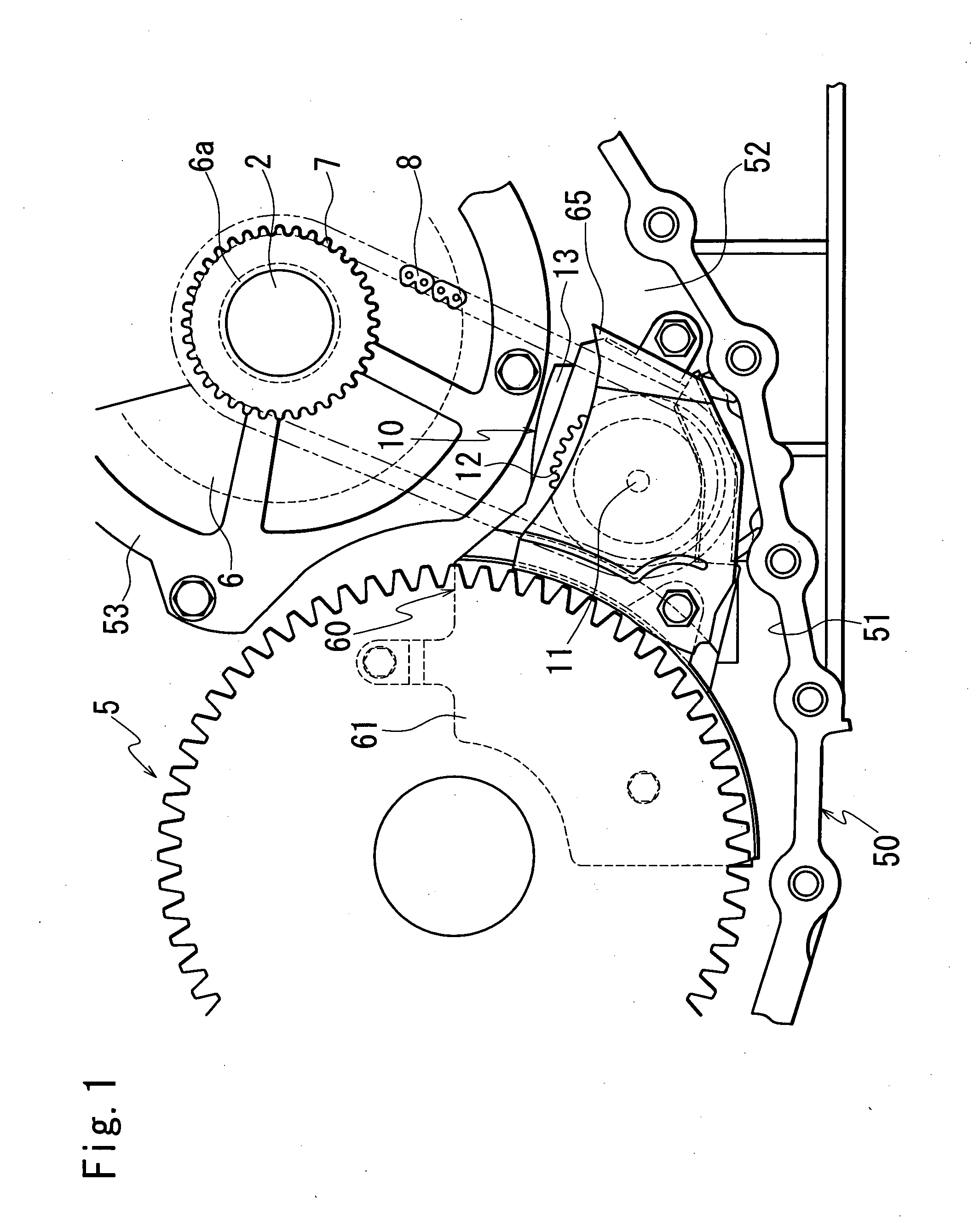
[0022]FIG. 1 is a front view showing a baffle plate according to an embodiment of the present invention.

[0023] Power from an engine, not shown, is transmitted to an input shaft (hereinafter referred to as a primary shaft) 2 of an automatic transmission through an after mentioned torque converter 6.

[0024] The power input to the primary shaft 2 is transmitted to a reduction gear, not shown, after engine revolutions are converted by a shift mechanism, not shown, comprised of a primary pulley provided on the primary shaft 2, a secondary pulley provided on a secondary shaft, and a V belt wound over the primary pulley and the secondary pulley. The reduction gear is engaged with a final gear 5 of a differential, so that power is transmitted from the reduction gear to the differential.

[0025] The power transmitted to the differential is transmitt...


PUM


Abstract

There is provided a baffle plate which conforms to the shape of the inner peripheral surface of a transmission case and can be easily brought into contact with the inner peripheral surface of the transmission case, making it easier to design and manufacture the baffle plate. Rubber plates are arranged on a side of the baffle plate in proximity to the bottom wall of the transmission case. The baffle plate encloses both sides of the rotating surface of the driven sprocket. Therefore, even if the inner peripheral surface of the bottom wall of the transmission case has a complex shape, the side of the baffle plate in proximity to the case bottom wall can be closely attached to the inner peripheral surface of the transmission case. And, the baffle plate can be easily designed and manufactured. Also, oil agitating resistance during rotation of the driven sprocket can be reduced.

Description

BACKGROUND OF THE INVENTION [0001] 1. Field of the Invention [0002] The present invention relates to a baffle plate which encloses rotating bodies in an automatic transmission. [0003] 2. Description of the Prior Art [0004] Conventionally, there has been known a plate which encloses rotating bodies such as a final gear in an automatic transmission (hereinafter referred to as “baffle plate”). The baffle plate prevents oil from flowing to the rotating bodies when the rotating bodies are rotating at high speed. As a result, the amount of oil agitated by the rotating bodies is decreased to reduce friction. [0005] Also, there has been known a baffle plate in which an opening is formed in part of the baffle plate and brought into contact with the inner peripheral surface of a transmission case to use the transmission case as part of the baffle plate so that the baffle plate can be compact. [0006] In this case, the opening of the baffle plate is formed to conform to the shape of the inner p...

Claims


Application Information

Patent Timeline
IPC IPC(8): F16N7/28F16H57/02F16H57/04
CPCF16H57/0423
Inventor TOMINAGA, MASAKAZUTAGUCHI, HIROMIKUNII, YASUHIKO
Owner JATCO LTD
Learn More