
Host and motor for elevator

a technology of elevators and motors, which is applied in the direction of hoisting equipment, manufacturing tools, transportation and packaging, etc., can solve the problems of increasing the amount of space occupied by the hoistway, and increasing the so-called dead space within the hoistway

Active Publication Date: 2006-03-23
MITSUBISHI ELECTRIC CORP
View PDF6 Cites 16 Cited by
  • Summary
  • Abstract
  • Description
  • Claims
  • Application Information

AI Technical Summary

Benefits of technology

[0007] The present invention resolves the problems described above of the conventional thin type elevator hoisting machines. An object of the present invention is to obtain a thin type elevator hoisting machine that is thinner than conventional thin type elevator hoisting machines, with few types of large size component parts, and having a housing that does not become an obstacle during installation and maintenance.

Problems solved by technology

However, the torque necessary for the elevator hoisting machine becomes larger, and although the elevator hoisting machine can be called thin, the absolute thickness gradually becomes larger.
However, the amount of space occupied as the hoistway, the so-called dead space within the hoistway, increases, whether or not in actual use, with increasing thickness of the elevator hoisting machine.

Method used


Image

  • Host and motor for elevator
  • Host and motor for elevator
  • Host and motor for elevator

Examples


embodiment 1

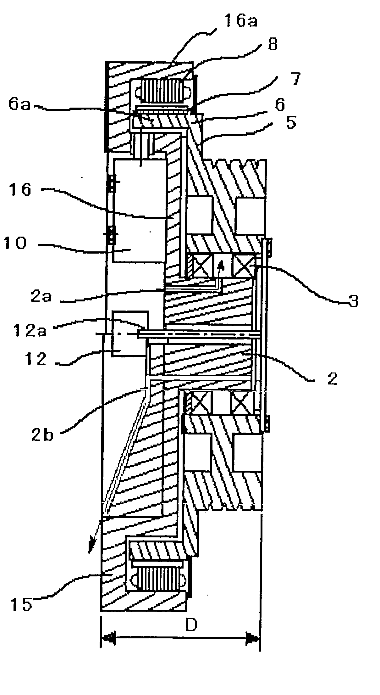
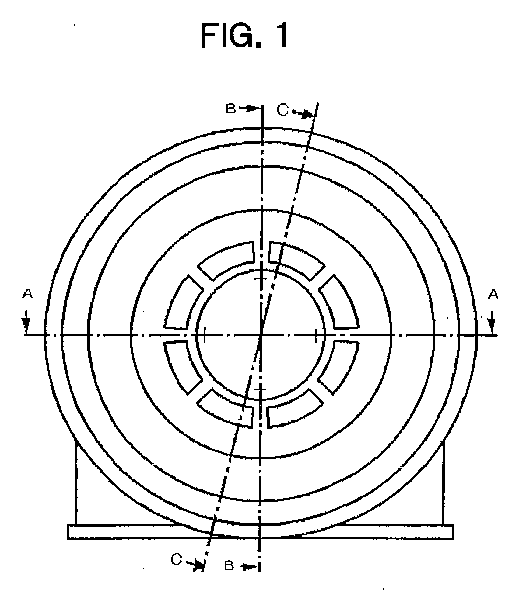
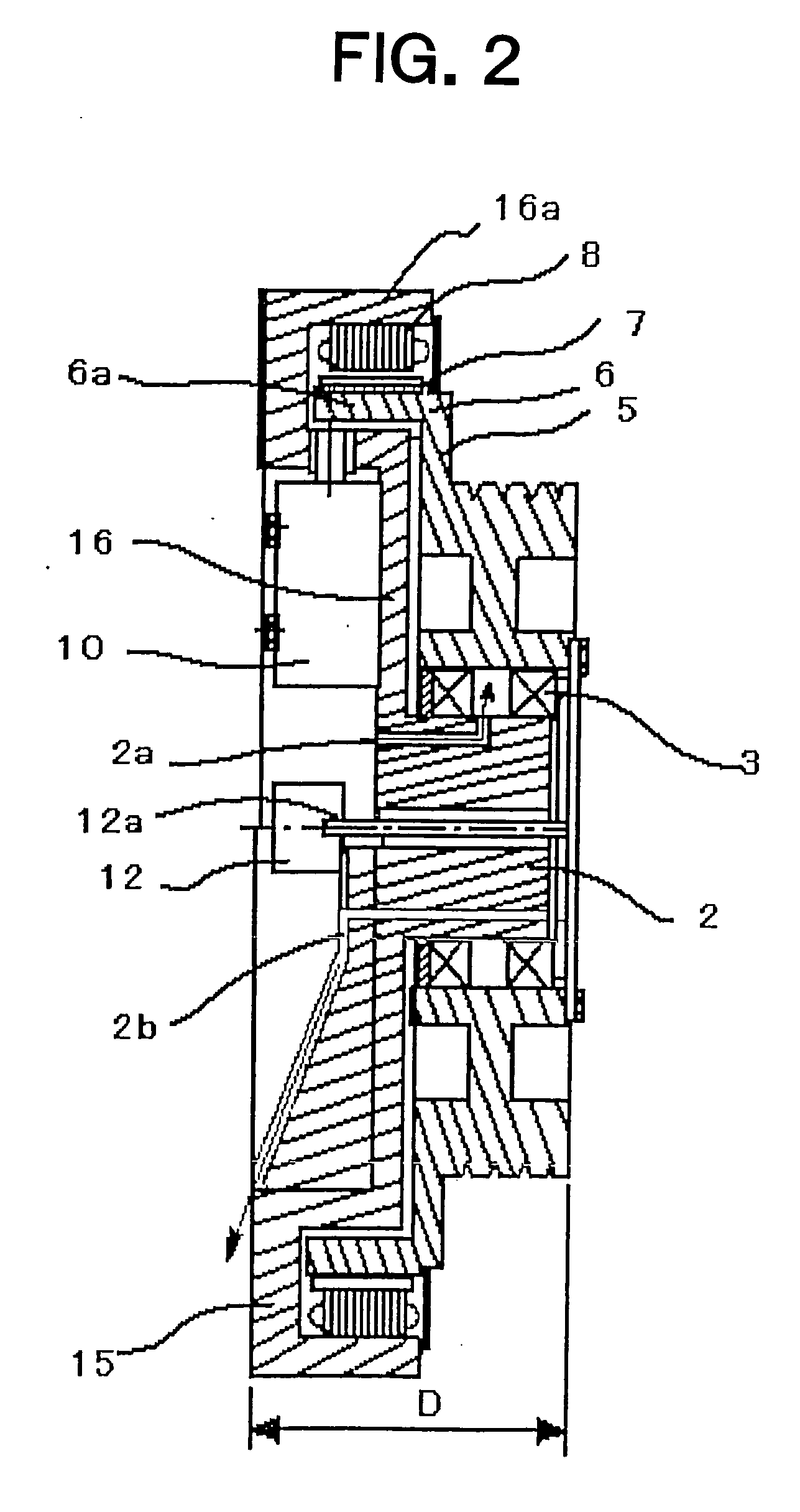
[0023] Embodiment 1 of the present invention is explained using FIG. 1 to FIG. 7. FIG. 1 is a front elevation view of a thin type elevator hoisting machine of the present invention, FIG. 2 is a cross sectional view of the thin type elevator hoisting machine shown in FIG. 1 taken along A-O-B, FIG. 3 is a cross sectional view of the thin type elevator hoisting machine shown in FIG. 1 taken along A-O-A, and FIG. 4 is across sectional view of the thin type elevator hoisting machine shown in FIG. 1 taken along C-O-C.

[0024] As shown in FIG. 3, the hoisting machine is provided with a rotation member 5, a fixed member 15, and a bearing 3. The fixed member 15 is provided with a stator 8, a fixed frame member 16 in which a stator mounting portion 16a, to which the stator 8 is mounted, and a fixed main shaft 2 are integrated, a brake device 10 mounted to the fixed frame member 16, and an encoder 12. The rotation member 5 is provided with a rotation support frame 6 in which a rotor 7 and a rot...

embodiment 2

[0043]FIG. 8 is a cross sectional view of a thin type elevator hoisting machine of embodiment 2 of the present invention. The sheave 4 and the rotation support frame 6 are separate members here.

[0044] The sheave 4 and the rotation support frame 6 are securely fastened together. The number of parts becomes larger compared to the number in embodiment 1, but there is an advantage in that it is easy to handle a change in the number of ropes wound about the sheave 4.

embodiment 3

[0045]FIG. 9 is a cross sectional view of a thin type elevator hoisting machine of embodiment 3 of the present invention. The brake device 10 has a structure in which the brake main body portion 10c is tightly fastened to a brake attachment plate 19. The brake attachment plate 19 and the fixed portion frame member 16 are joined, thus forming a rigid closed structure. The brake device 10 and the brake attachment plate 19 are separate members, and handling thereof is easy compared to the integrated brake device shown in embodiment 1.


PUM


Abstract

A thin type elevator hoisting machine is provided with a stator mounting portion at which a stator core of a motor is mounted to a surface of a side opposite to a sheave in a sheave rotation centerline direction of the hoisting machine, characterized in that a hat shape fixed frame member in which the stator mounting portion and a fixed main shaft that supports rotation of a rotor through a bearing are integrated. The thin type elevator hoisting machine is characterized in that a brake device in which an inner radial surface of a cylindrical rotor mounting portion forms a braking surface. A motor is characterized in that the width of a magnet constituting a rotor is larger than the width of the stator core. The thin type elevator hoisting machine is provided with the motor.

Description

TECHNICAL FIELD [0001] The present invention relates to a thin type elevator hoisting machine mainly used in a machine room-less elevator. BACKGROUND ART [0002]FIG. 12 is a front elevation view of a conventional thin type hoisting machine for an elevator, disclosed in JP 2000-289954 A, for example, FIG. 13 is a cross sectional view for explaining a structure of the hoisting machine, and FIG. 14 is an enlarged view of a vicinity of a stator core of a motor section of the elevator hoisting machine. [0003] A fixed main shaft 2 is securely fastened to a cup shape housing 1. A sheave 4, which is a portion of a rotation member 5, is mounted about the fixed main shaft 2, through a bearing 3. The housing 1 has a shape that covers the sheave 4, and a main rope that hauls the elevator enters and exits through an opening portion 1a opened in a portion of the housing 1. One end of a side opposite to a position at which the fixed main shaft 2 and the housing 1 are securely fastened together beco...

Claims


Application Information

Patent Timeline
Patent Type & Authority Applications(United States)
IPC IPC(8): B66B11/08B66B11/04H02K7/10H02K7/102H02K21/14
CPCB66B11/043B66B11/0438H02K21/14H02K7/102H02K7/1023H02K7/1008Y10S254/901
Inventor HASHIGUCHI, NAOKI
Owner MITSUBISHI ELECTRIC CORP
Learn More