Low fill factor wire grid polarizer and method of use

a low-fill factor, wire-grid technology, applied in the field of polarizers, can solve the problems of affecting the overall brightness of the image, affecting the polarization recycling process, and unable to recover lost light from the light sour

Active Publication Date: 2006-03-23
SK MICROWORKS SOLUTIONS CO LTD
View PDF16 Cites 113 Cited by
  • Summary
  • Abstract
  • Description
  • Claims
  • Application Information

AI Technical Summary

Benefits of technology

[0010] In accordance with an example embodiment, a wire grid polarizer includes a plurality of parallel conductors having a pitch (P), a width (W), and a height (H). In example embodiments, a fill-factor (W / P) is greater than approximately 0.18 and less than approximately 0.25.
[0011] In accordance with another example embodiment, a display system includes a light source and a light-valve. The display system also includes a wire grid polarizer that includes a plurality of parallel conductors having a pitch (P), a width (W), and a height (H). In example embodiments, a fill-factor (W / P) is greater than approximately 0.18 and less than approximately 0.25.

Problems solved by technology

While LCD devices are becoming ubiquitous in display and microdisplay applications, there are certain drawbacks associated with known devices.
For example, in known devices some of the light from the light source may be irrecoverably lost and the overall brightness of the image adversely impacted.
In known systems using reflective polarizers, there are competing objectives that impede the polarization recycling.
Such known wire-grid polarizers are not desirable in light recycling because the total light throughput is unacceptably low.
This can result in unacceptable contrast and brightness in the viewed image.
Such known plastic polarizers are not desirable in light recycling when used with very strong backlights as the plastics can ‘yellow’ due to light absorption.
This can result in unacceptable coloration of the viewed image.
As such, the need for improved light throughput and stability of coloration has not been met via known devices and structures.

Method used


Image

  • Low fill factor wire grid polarizer and method of use
  • Low fill factor wire grid polarizer and method of use
  • Low fill factor wire grid polarizer and method of use

Examples


Embodiment Construction

[0035] In the following detailed description, for purposes of explanation and not limitation, example embodiments disclosing specific details are set forth in order to provide a thorough understanding of the present invention. However, it will be apparent to one having ordinary skill in the art having had the benefit of the present disclosure, that the present invention may be practiced in other embodiments that depart from the specific details disclosed herein. Moreover, descriptions of well-known apparati and methods may be omitted so as to not obscure the description of the example embodiments. Such methods and apparati are clearly within the contemplation of the inventors in carrying out the example embodiments. Wherever possible, like numerals refer to like features throughout.

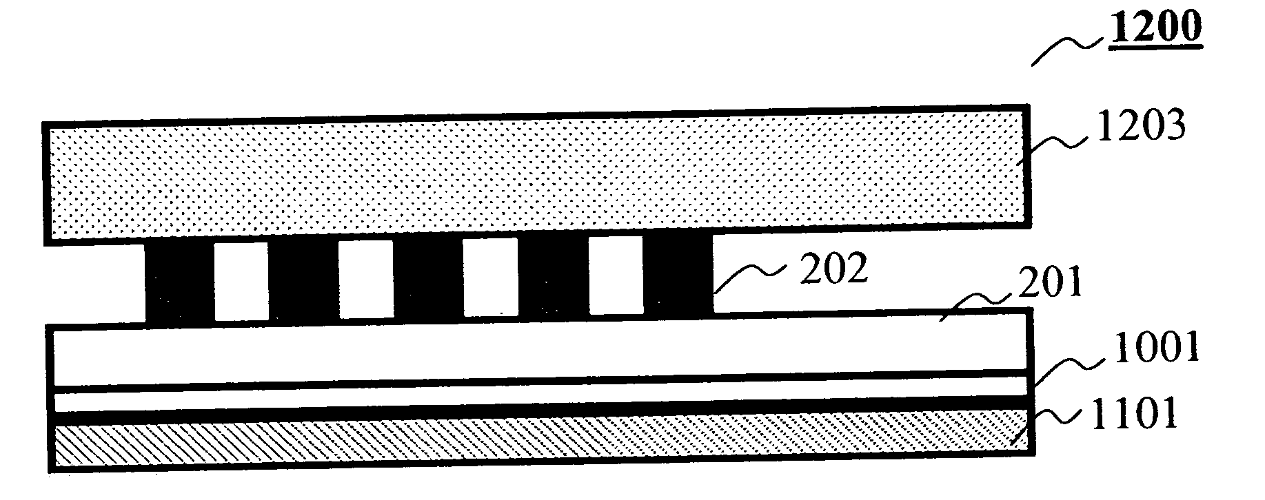
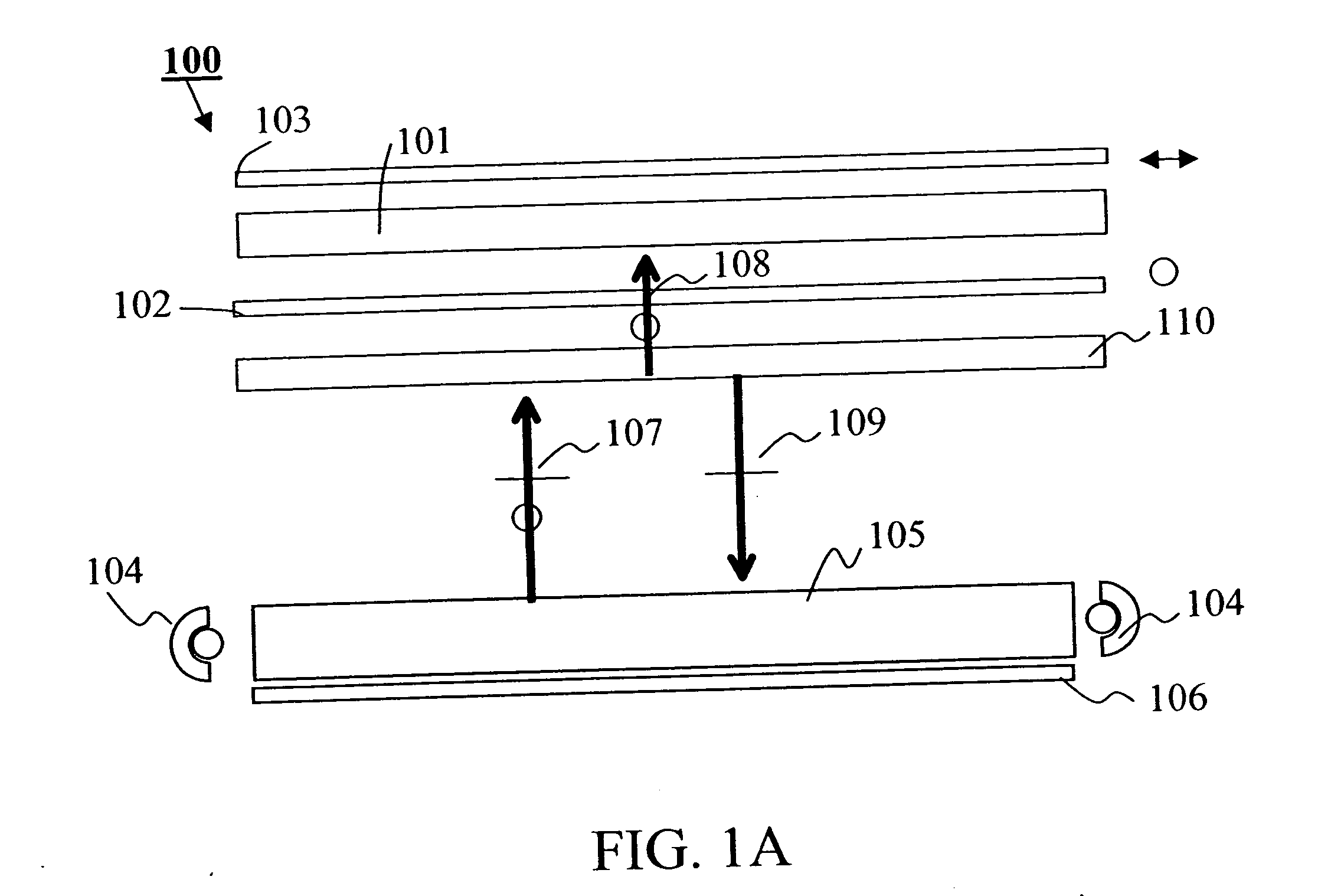
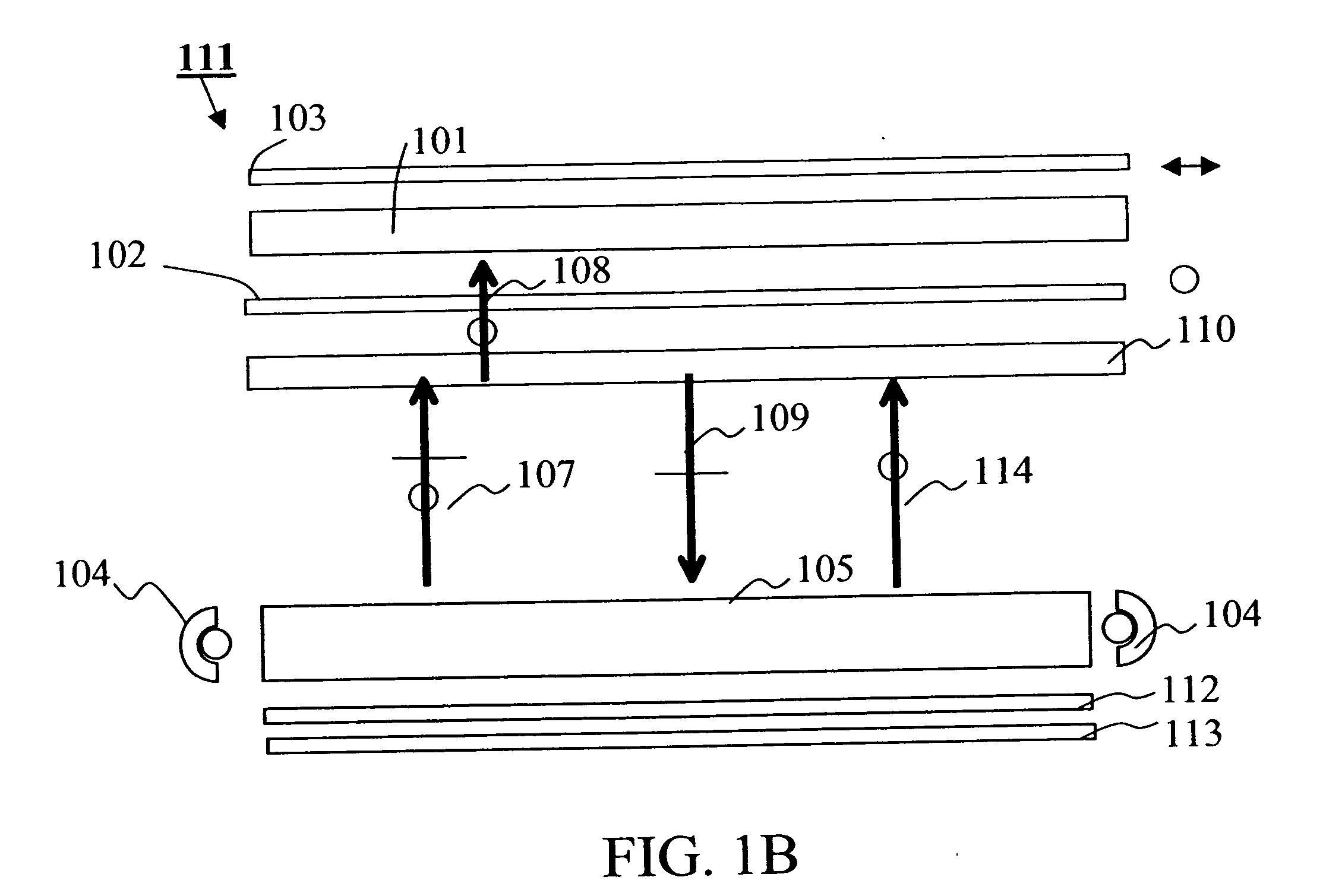
[0036] Briefly, and as described in detail in conjunction with example embodiments, a wire grid polarizer and a display system including a wire grid polarizer are disclosed. The wire grid polarizer inclu...


PUM


Abstract

In an example embodiment, a wire grid polarizer includes a plurality of parallel conductors having a pitch (P), a width (W), and a height (H). In example embodiments, a fill-factor (W/P) is greater than approximately 0.18 and less than approximately 0.25. In another example embodiment, a display system includes a light source and a light-valve. The display system also includes a wire grid polarizer that includes a plurality of parallel conductors having a pitch (P), a width (W), and a height (H). In example embodiments, a fill-factor (W/P) is greater than approximately 0.18 and less than approximately 0.25.

Description

FIELD OF THE INVENTION [0001] A polarizer is described for use in enhancing light efficiency. BACKGROUND OF THE INVENTION [0002] Light-valves are implemented in a wide variety of display technologies. For example, display and microdisplay panels are gaining in popularity in many applications such as televisions, computer monitors, point of sale displays, personal digital assistants and electronic cinema to mention a few applications. [0003] Many light valves are based on liquid crystal (LC) technologies. In some LC technologies light is transmitted through an LC device (panel), while in others the light traverses the panel twice, after being reflected at a far surface of the panel. [0004] In operation, an external field or voltage is used to selectively rotate the axes of the molecules of the LC material. As is well known, by application of this voltage across the LC panel, the direction of the LC molecules can be controlled and the state of polarization of the reflected light is se...

Claims


Application Information

Patent Timeline
Patent Type & Authority Applications(United States)
IPC IPC(8): G02B5/30
CPCG02F1/133528G02B5/3058G02B5/30
Inventor MI, XIANG-DONGKESSLER, DAVIDTUTT, LEE W.WELLER-BROPHY, LAURA A.
Owner SK MICROWORKS SOLUTIONS CO LTD
Why Eureka
Try Eureka