
Power supply circuit device for eliminating electrical interference

a power supply circuit and electrical interference technology, applied in the direction of overvoltage protection resistors, emergency protective arrangements for limiting excess voltage/current, and arrangements responsive to excess voltage, can solve problems such as noise, interference, and uneven hue on the display, and achieve the effect of removing potential electrical interferen

Inactive Publication Date: 2006-03-23
ZIPPY TECH
View PDF8 Cites 3 Cited by
  • Summary
  • Abstract
  • Description
  • Claims
  • Application Information

AI Technical Summary

Benefits of technology

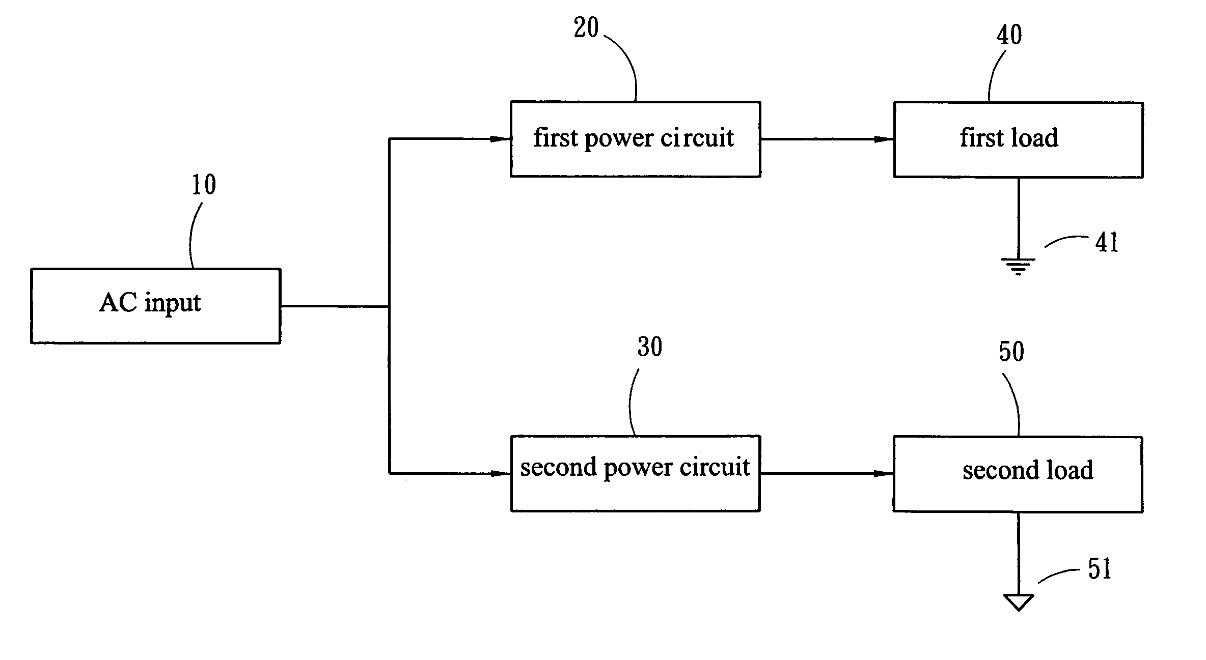
[0005] It is therefore an object of the present invention to provide a power supply circuit having a first load of low voltage and a second load of high voltage in which both loads are grounded independently. Also, the power supply circuit comprises two parallel power paths in which one is connected to the first load via a first power circuit and the other one is connected to the second load via a second power circuit. By grounding the first and second loads independently, it is possible of eliminating a potential electrical interference in the first load.
[0006] It is another object of the present invention to provide a power supply circuit in which a single switch is provided for turning on or off all components of an electronic device (e.g., AV product) incorporating the power supply circuit of the present invention in one operation without adversely affecting efficiency and quality of the display thereof.

Problems solved by technology

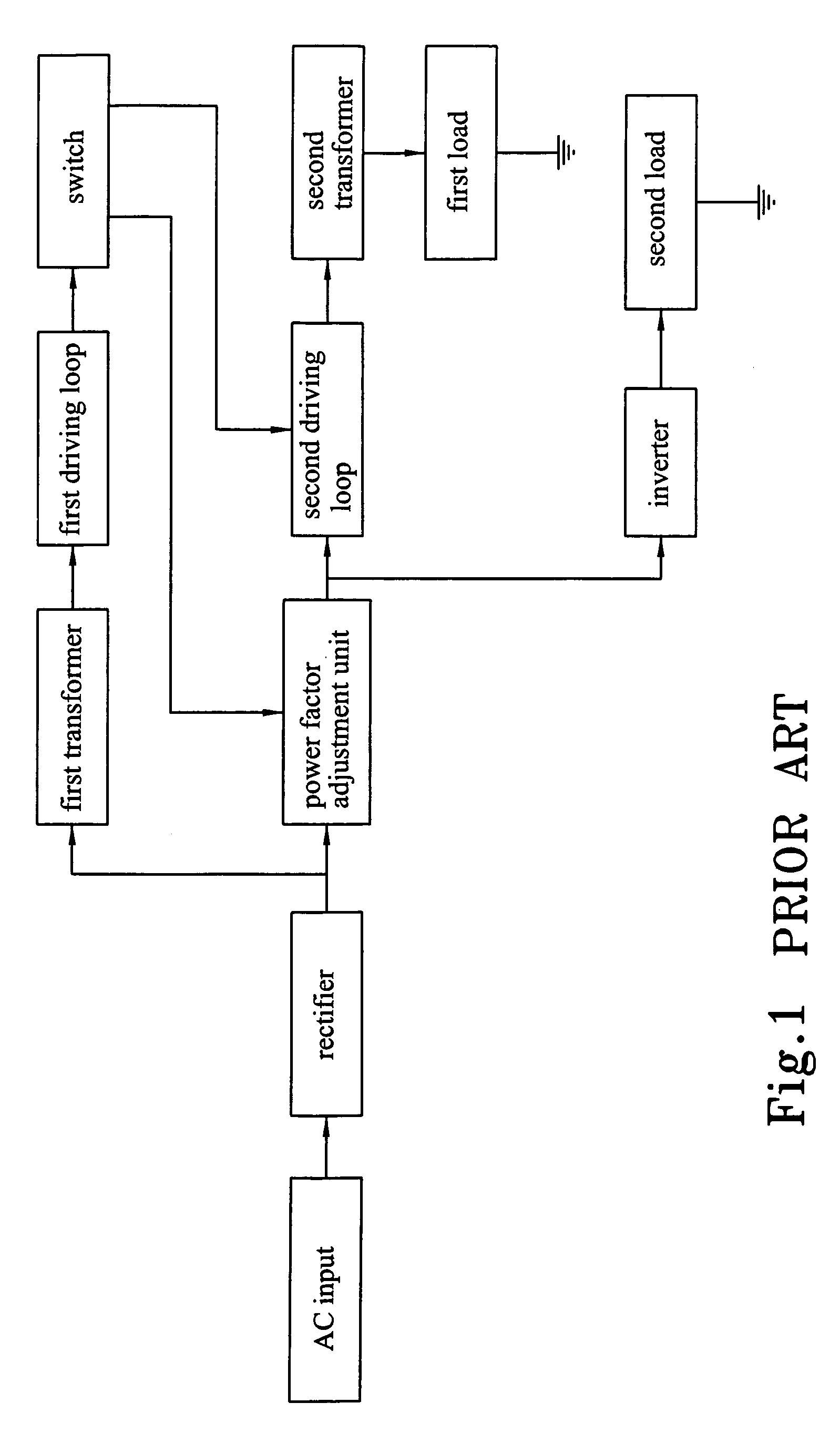
Otherwise, it may be interfered, for example by fluctuation voltage occurred on the second load of high voltage, resulting in ripples and uneven hue on the display, poor speaker output quality, noise, etc.
The interference is occurred because the voltage increase of the inverter is achieved by oscillating wave which adversely affects the first load via the common ground.
That is, the first load is interfered by the voltage increase in the inverter.
Such drawback is even serious in a large screen display of TV.

Method used


Image

  • Power supply circuit device for eliminating electrical interference
  • Power supply circuit device for eliminating electrical interference
  • Power supply circuit device for eliminating electrical interference

Examples


Embodiment Construction

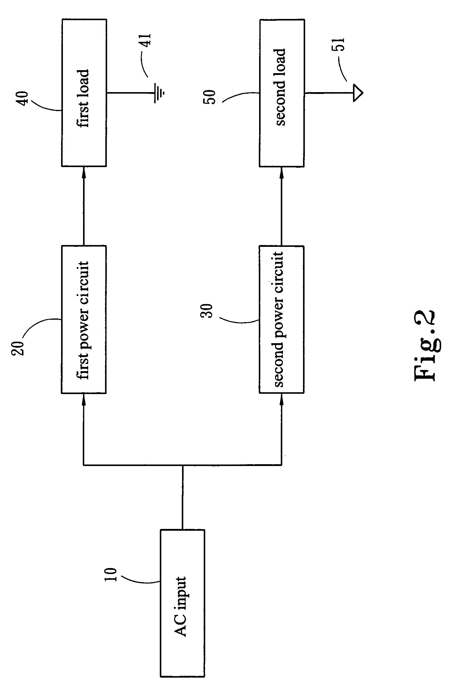
[0013] Referring to FIGS. 2 and 3, there is shown a power supply circuit constructed in accordance with a first preferred embodiment of the invention. The power supply circuit is installed in an AV product such as a LCD or LCD TV. As shown, an AC input 10 is connected to an external AC source. Two paths are in parallel with the AC input 10 in which one is connected to a first load 40 via a first power circuit 20 and the other is connected to a second load 50 via a second power circuit 30. The first power circuit 20 is adapted to convert AC into DC of low voltage and the second power circuit 30 is adapted to convert AC into DC of high voltage. Also, the ground terminal 41 of the first load 40 and the ground terminal 51 of the second load 50 are independent.

[0014] As shown in FIG. 3 specifically, the first power circuit 20 comprises a first rectifier 21 connected to the AC input 10, a predetermined power supply unit 22 and a first power supply unit 23, and a switch 24 connected to bo...


PUM


Abstract

A power supply circuit device for eliminating electrical interference which is connected to an AC input and comprises a first power circuit comprising a first rectifier connected to the AC input for generating a rectified DC, a predetermined power supply unit, a first power supply unit being in parallel with the predetermined power supply unit and connected to a first load, and a switch connected to both the power supply units; and a second power circuit being in parallel with the first power circuit and comprising a second rectifier connected to the AC input for generating the rectified DC, and a second power supply unit connected to a second load. Both the first and second loads are activated by the first and second power supply units for prohibiting fluctuation voltage occurred on the second load from transmitting to the first load and interfering therewith.

Description

[0001] This application is a continuation-in-part, and claims priority, of from U.S. patent application Ser. No. 10 / 942,876 filed on Sep. 17, 2004, entitled “Power supply circuit for eliminating electrical interference”. FIELD OF THE INVENTION [0002] The present invention relates to power supply circuits and more particularly to such a power supply circuit, installed in an electronic device, capable of eliminating a potential electrical interference of one load by grounding the other load independently in which the loads have different operating voltages. BACKGROUND OF THE INVENTION [0003] A conventional power supply circuit of an AV (audio video) product such as a LCD (liquid crystal display) or LCD TV (television) is shown in FIG. 1. An AC input is connected to an external AC source. A rectifier including a plurality of diodes is connected to the AC input and is adapted to convert AC voltage into DC one having a wavy waveshape. A power factor adjustment unit is connected to the re...

Claims


Application Information

Patent Timeline
IPC IPC(8): H02H9/06H02H1/00
CPCH02J1/102
Inventor CHOU, CHIN-WENCHENG, YING-NANCHUNG, CHIN-BIAU
Owner ZIPPY TECH
Learn More