Image pickup apparatus and electronics apparatus mounting the same

a pickup apparatus and electronics technology, applied in the direction of digital signal error detection/correction, instruments, television systems, etc., can solve the problems of restricting the design and manufacturing of the sector drive unit, the shutter blade cannot move smoothly, etc., to and reduce the load applied to the sector

Inactive Publication Date: 2006-03-23
SEIKO HLDG KK TRADING AS SEIKO HLDG CORP
View PDF8 Cites 12 Cited by
  • Summary
  • Abstract
  • Description
  • Claims
  • Application Information

AI Technical Summary

Benefits of technology

[0007] The present invention has been made in view of the above circumstances and provides an image pickup apparatus and an electronics apparatus having the same, in which the load applied to the sector can be reduced.
[0008] According to one aspect of the present invention, preferably, there is provided an image pickup apparatus including an image pickup unit having an image pickup element, an optical unit having lenses, a sector drive unit having sectors arranged in a space for arranging the sectors, and supporting members being fixed in the space for arranging the sectors and having lengths equal to at least a width of the space for arranging the sectors in a light axis direction. With the supporting members, the space for arranging the sectors can be retained and loads to be applied on the sectors can be alleviated.
[0009] According to another aspect of the present invention, preferably, there is provided an electronics apparatus comprising the above-mentioned image pickup apparatus. The supporting members may protrude from the space for arranging the sectors in the light axis direction and be in contact with a chassis of the electronics apparatus. This makes it possible to fix the image pickup apparatus onto the chassis stably and reduce the loads to be applied on the sectors.

Problems solved by technology

The conventional image pickup apparatus includes the sector drive unit arranged between other component elements, resulting in restrictions in design and manufacturing of the sector drive unit.
This arises the problem in that the shutter blade cannot move smoothly.

Method used


Image

  • Image pickup apparatus and electronics apparatus mounting the same
  • Image pickup apparatus and electronics apparatus mounting the same
  • Image pickup apparatus and electronics apparatus mounting the same

Examples


Embodiment Construction

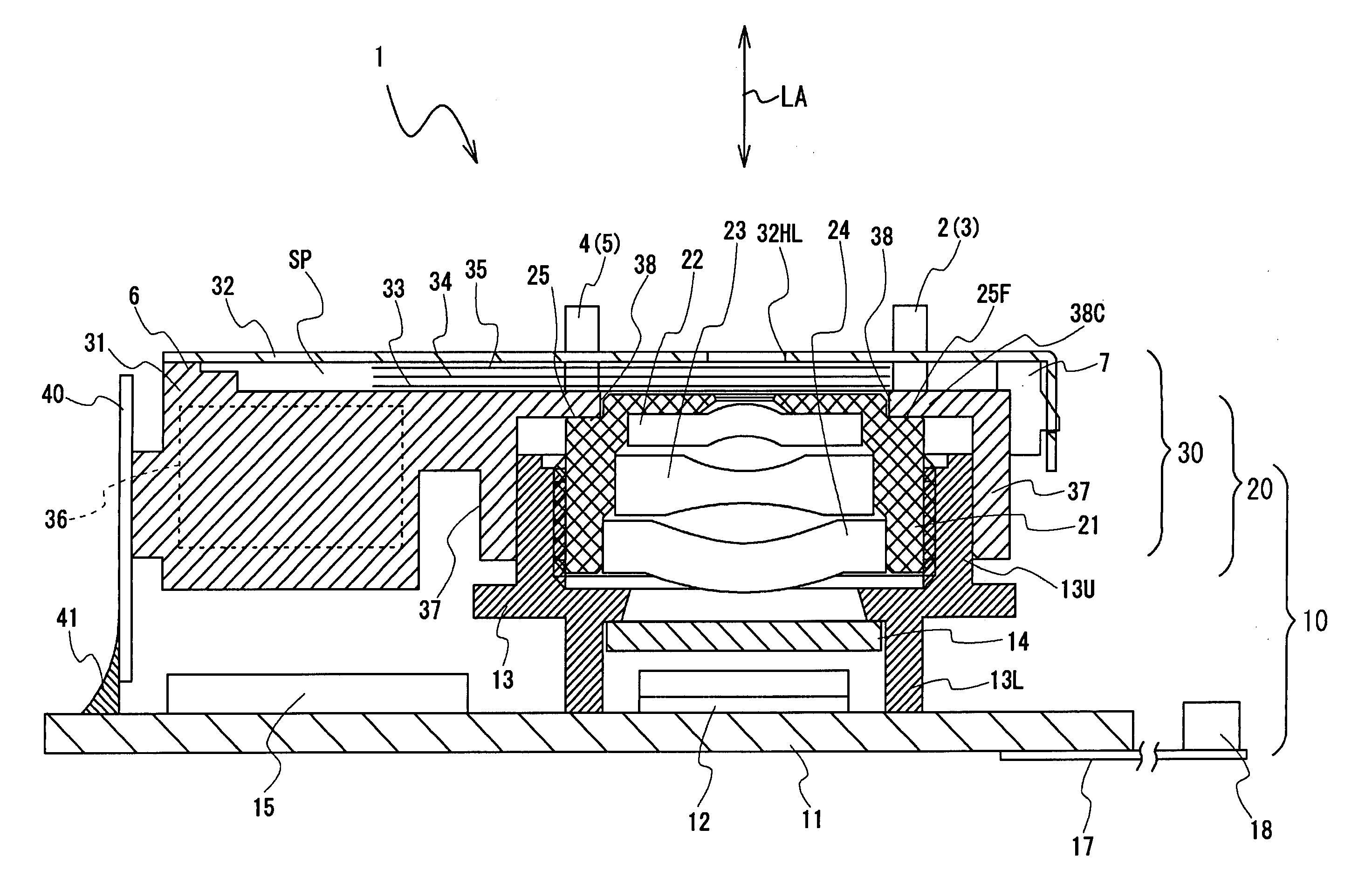
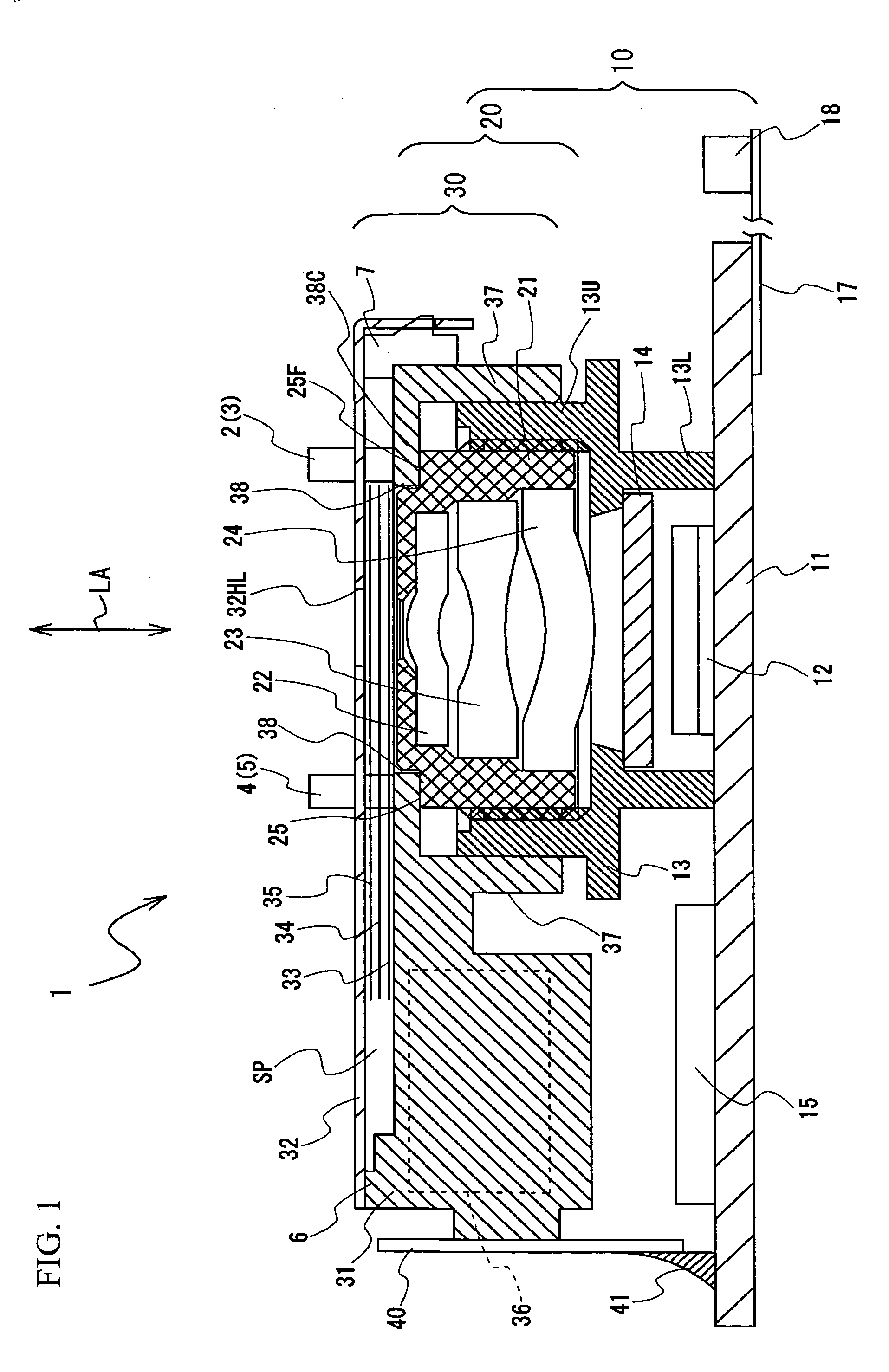
[0019] A description will now be given, with reference to the accompanying drawings, of an embodiment of the present invention. FIG. 1 is a side view of an image pickup apparatus 1 to show the inside thereof. The image pickup apparatus 1 is configured to include three main units. That is to say, the image pickup apparatus 1 includes an image pickup unit 10 having an image pickup element therein, an optical unit 20 having lenses, and a sector drive unit 30 that drives the sector. Referring to FIG. 1, the image pickup unit 10, the optical unit 20, and the sector drive unit 3 are piled up in this order in the image pickup apparatus 1. The aforementioned three units are provided to partially overlap each other in upper and lower portions thereof. Here, the image pickup unit 10 and the optical unit 20 are referred to as an image pickup optical module.

[0020] The image pickup unit 10 includes an image pickup substrate 11, an image pickup element 12, a lens barrel 13, and an optical filter...


PUM

PropertyMeasurementUnit
lengthsaaaaaaaaaa
widthaaaaaaaaaa
outer circumferenceaaaaaaaaaa

Abstract

There is provided an image pickup apparatus having an image pickup unit having an image pickup element, an optical unit having lenses, a sector drive unit having sectors arranged in a space for arranging the sectors, and supporting members being fixed in the space for arranging the sectors and having lengths equal to at least a width of the space for arranging the sectors in a light axis direction.

Description

BACKGROUND OF THE INVENTION [0001] 1. Field of the Invention [0002] This invention generally relates to image pickup apparatuses and electronics apparatuses mounting the same, and more particularly, to an image pickup unit having a sector, also known as shutter blade, on a subject side of a lens. [0003] 2. Description of the Related Art [0004] Conventionally, a general image pickup apparatus includes the sector arranged between an optical unit having the lens and the image pickup unit having an image pickup element. In order to move the shutter blade, a sector drive unit, also known as shutter device, has to be composed of a substrate that supports the sector and a drive source such as step motor. The conventional image pickup apparatus includes the sector drive unit arranged between other component elements, resulting in restrictions in design and manufacturing of the sector drive unit. [0005] Japanese Patent Application Publication No. 2004-15602 (hereinafter referred to as Docume...

Claims


Application Information

Patent Timeline
Patent Type & Authority Applications(United States)
IPC IPC(8): G11B7/00
CPCH04N5/2254H04N23/55
Inventor TAKAHASHI, HIROSHINAKANO, YOICHIKUDOU, KENICHIFUJIWARA, MASAO
Owner SEIKO HLDG KK TRADING AS SEIKO HLDG CORP
Why Eureka
Try Eureka