Environmentally sealed terminating device and sealing gel

a terminating device and sealing gel technology, applied in the direction of coupling device details, coupling device connections, contact members penetrating/cutting insulation/cable strands, etc., can solve the problems of not being nid or bet may be exposed to dust, dirt, moisture and other deleterious environmental effects, and subscribers are no longer able to access the communications network

Active Publication Date: 2006-03-23
CORNING OPTICAL COMM LLC
View PDF13 Cites 12 Cited by
  • Summary
  • Abstract
  • Description
  • Claims
  • Application Information

AI Technical Summary

Benefits of technology

[0016] In yet another broad aspect of the invention, the invention is embodied in a method of environmentally sealing a terminating device comprising providing a terminating device having a base, at least one pair of insulation displacement contacts disposed within the base, and a means for engaging at least one conductive wire in a corresponding one of the insulation displacement contacts. The method further includes encapsulating the at least one pair of insulation displacement contacts with a silicone environmental sealing gel characterized by a dynamic crossover point between about 1 rad / sec and 20 rad / sec at any temperature in the range between about −40° C. to about 80° C., a dynamic loss modulus G″ greater than a dynamic storage modulus G′ at a shear frequency greater than the dynamic crossover point and less than the dynamic storage modulus G′ at a shear frequency less than the dynamic crossover point at any temperature in the range between about −40° C. to about 80° C., an ultimate elongation greater than about 1000%, an ultimate tensile strength greater than about 2 psi, and a cone penetration value expressed in tenths of a millimeter between about 255 and 265 at 23° C.
[0017] The invention will be understood more easily and other objects, characteristics, details and advantages thereof will become more clearly apparent in the course of the following explanatory description, which is given, without in any way implying a limitation to the intended scope of the invention, with reference to the attached drawings.

Problems solved by technology

The NID or BET may be further provided with an outer cover that is accessible to both service provider personnel and the subscriber, but is not accessible to unauthorized persons.
The NID or BET may be exposed to dust, dirt, moisture and other deleterious environmental effects.
When a terminating device fails, the subscriber is no longer able to access the communications network.
Further, the service provider must dispatch a technician to the subscriber site to repair or replace the terminating device, at significant expense to the service provider.
In spite of the advances in the designs of terminating devices, the protecting gels utilized thus far have either been too fluid to be retained within the terminating device without leakage, or lack visco-elastic properties that permit proper connection of the provider or subscriber wiring within the terminating device.
For example, in the embodiments of the terminating device disclosed in U.S. Pat. No. 6,500,020, a protecting gel that is too stiff impedes the movement of the actuating components and therefore requires an excessive force to terminate the wiring within the conductive contacts.
However, a protecting gel that is too elastic generates an excessive restoring force that prevents proper or consistent termination of the wiring.

Method used


Image

  • Environmentally sealed terminating device and sealing gel
  • Environmentally sealed terminating device and sealing gel
  • Environmentally sealed terminating device and sealing gel

Examples


Embodiment Construction

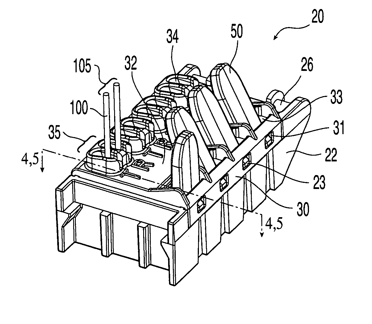
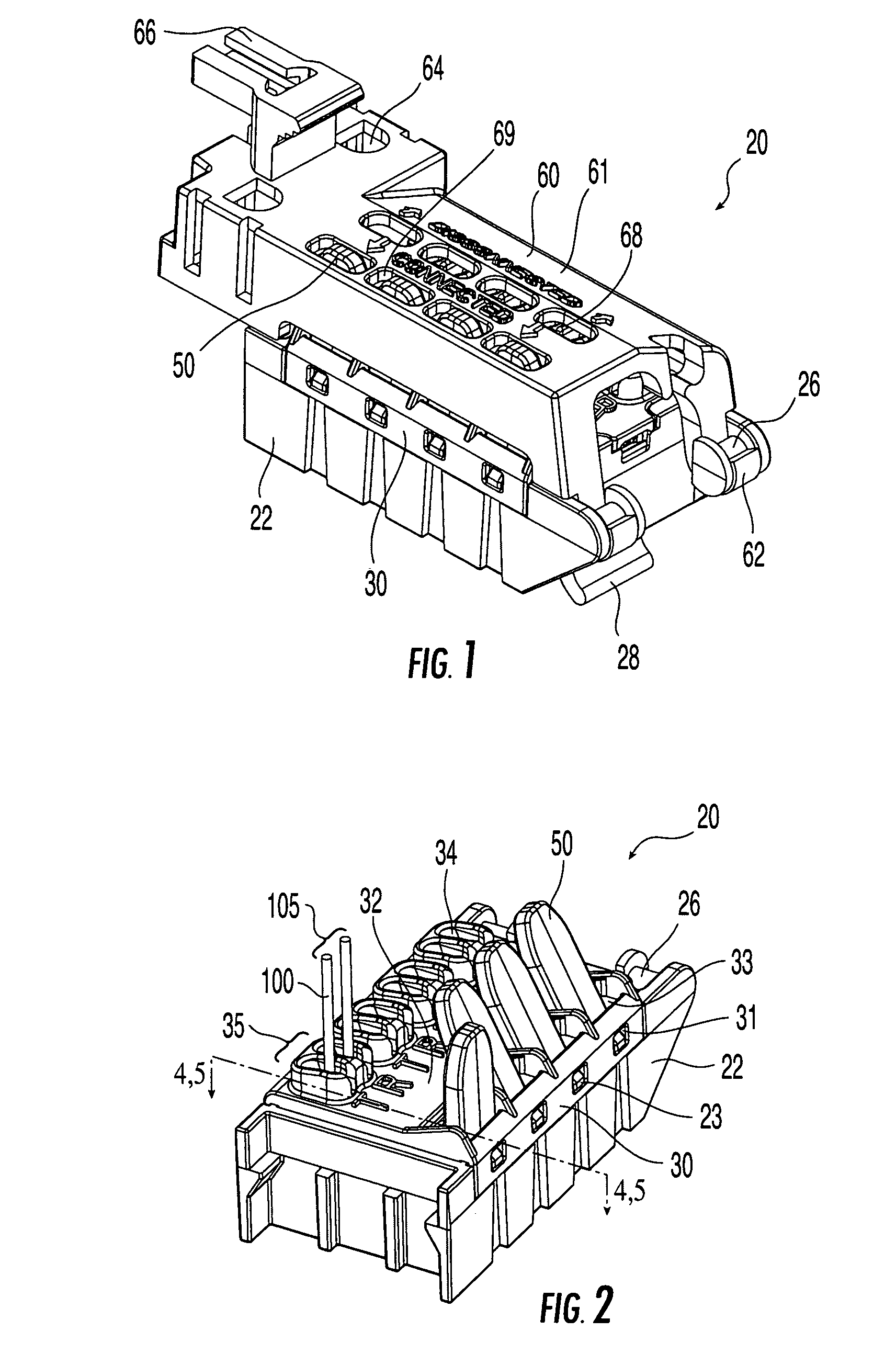
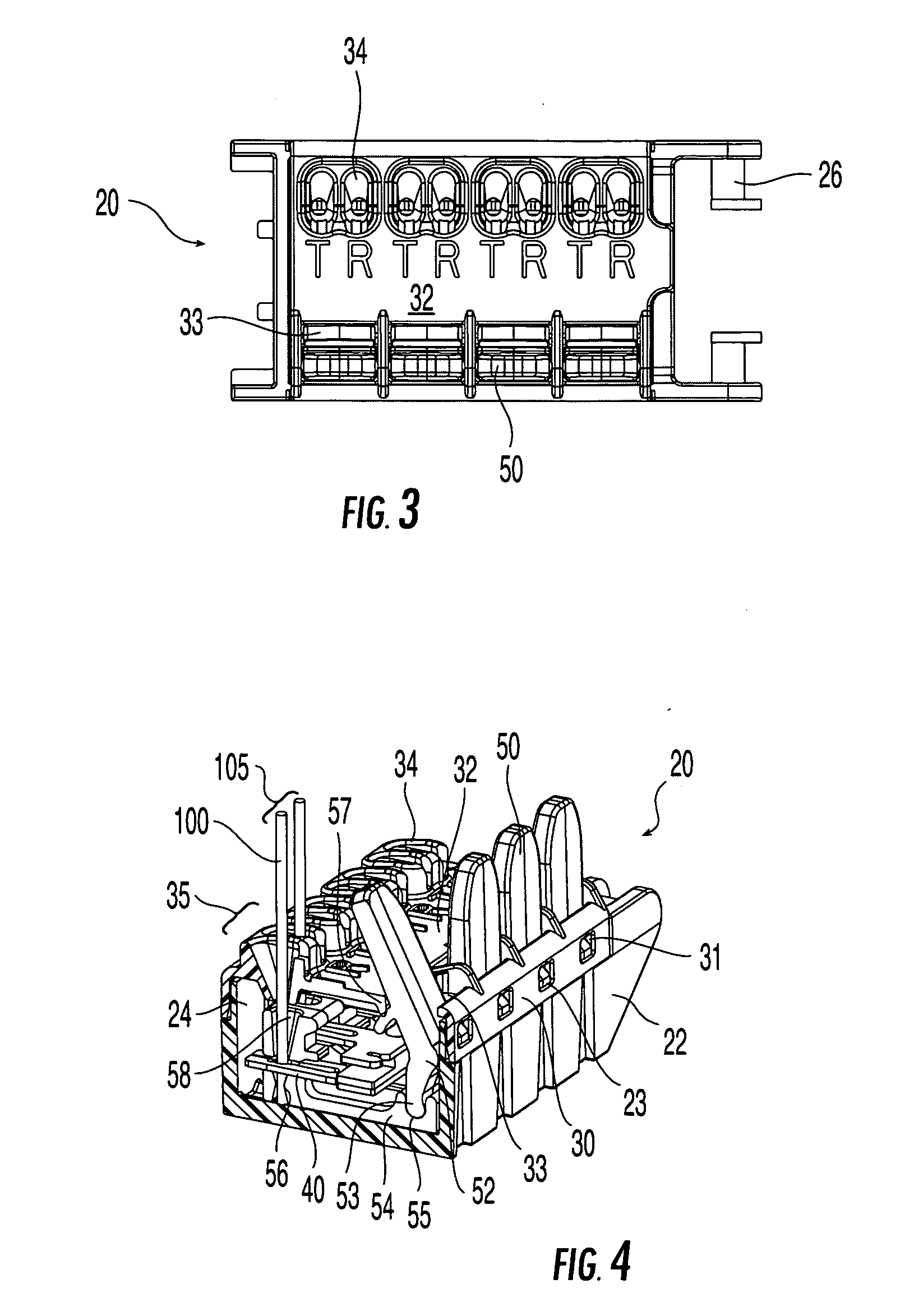
[0033]FIGS. 1-5 illustrate an exemplary customer bridge as disclosed in U.S. Pat. No. 6,500,020, indicated generally by reference numeral 20. Embodiments of the present invention shall be described with reference to exemplary customer bridge 20. However, the skilled artisan will realize that the protective sealing gel according to the present invention is equally suitable for other terminating device designs, and customer bridge 20 should not be considered limiting in this regard.

[0034] Customer bridge 20 is sometimes referred to in the art as an interconnect module, a connector module, a terminating module, or a wiring module. As used herein, the term “customer bridge” is intended to include any apparatus for terminating provider and subscriber wiring in a communications network, including but not limited to an interconnect module, a connector module, a wiring module, or a customer bridge. In the exemplary embodiment illustrated and described herein, customer bridge 20 is used to ...


PUM

PropertyMeasurementUnit
temperatureaaaaaaaaaa

Abstract

A terminating device for terminating subscriber wiring to pairs of insulation displacement type conductive contacts includes a protective sealing gel disposed within the terminating device. The gel encapsulates the conductive contacts and is characterized by a dynamic storage modulus G′ and a dynamic loss modulus G″ expressed in dynes/cm2 having a dynamic crossover point between about 1 rad/sec and about 20 rad/sec at any temperature in the range between about −40° C. to about 80° C. The loss modulus G″ is greater than the storage modulus G′ at a shear frequency greater than the dynamic crossover point and is less than the storage modulus G′ at a shear frequency less than the dynamic crossover point. The gel has an ultimate elongation greater than about 1000%, an ultimate tensile strength greater than about 2 psi, and a cone penetration value expressed in tenths of a millimeter between about 255 and 265.

Description

BACKGROUND OF THE INVENTION [0001] 1. Field of the Invention [0002] The present invention relates to an environmentally sealed terminating device, and in particular to a terminating device sealed with a protective silicone gel. [0003] 2. Technical Background [0004] A communications service provider, such as a telephone company, may offer both voice and data transmission services over a communications network. Customers of the service provider, commonly referred to as “subscribers,” may purchase as many communications services as they desire and equip their homes, businesses, or the like with equipment to utilize such services. Subscribers are responsible for proper operation of the equipment and the service provider is responsible for proper operation of the communications network up to the interface, commonly referred to as the “demarcation point,” between the service provider wiring and the subscriber wiring. The demarcation point is accessible to both the subscriber and the servi...

Claims


Application Information

Patent Timeline
Patent Type & Authority Applications(United States)
IPC IPC(8): H01R4/24
CPCC08G77/12C08G77/20C08G2220/00C08L83/04H01R4/2433H01R13/5216H04Q1/20H04Q1/028H04Q1/141H04M2207/20H04Q1/021H04Q1/11C08L83/00
Inventor LIU, ZIWEIHUSPENI, PAUL J.
Owner CORNING OPTICAL COMM LLC
Why Eureka
Try Eureka