Blasting nozzle

a technology of a nozzle and a nozzle body, which is applied in the direction of spray nozzles, blast generating devices, abrasives, etc., can solve the problems of common damage, affecting the use of nozzles, and the underlying surface tends to be damaged, so as to achieve greater cleaning power, increase the quantity of grit, and increase the quantity of abrasives

Inactive Publication Date: 2006-03-23
QUILL INTERNATIONAL INDUSTRIES PLC
View PDF3 Cites 42 Cited by
  • Summary
  • Abstract
  • Description
  • Claims
  • Application Information

AI Technical Summary

Benefits of technology

[0010] In such a nozzle, in the outlet portion much of the accelerated abrasive-laden gaseous jet tends to be directed by the splitter means into one or other of the two lobes, which are conjoined at the location of the splitter means so that they still form a single jet. However, some of the jet will still travel centrally down the nozzle. Hence, the abrasive distribution transversely across the jet within each of the areas defined by the lobes of the outlet orifice will define a standard bell-shaped distribution curve distribution as will the jet as a whole. Hence, with a two-lobed outlet orifice the abrasive distribution defines a curve made up of three overlapping bell-shaped distributions and similarly for outlet portions defining three or more lobes. The abrasive distribution across the whole of the outlet orifice is therefore more even than that in the prior art nozzles. The effect of this is that apart from the advantages of applying a jet with a more even abrasive distribution pattern, it also enables a greater quantity of abrasive to be entrained in any given fluid jet. Conventionally, when the central portion of the jet is fully abrasive laden, the jet cannot entrain any more without being choked. However, in the present invention, the more even distribution of the abrasive across the jet lowers the actual proportion of abrasive in any given part of the jet which means that it is capable of entraining a greater quantity. Hence, in use an operator need not repeatedly blast the same area of the surface to be blasted to the same extent as prior art nozzles to achieve an appropriate level of cleaning. Such a manner of working tends to damage the underlying surface because some areas will be blasted by a high level of abrasive to enable other areas to receive a minimum level. As a result, the nozzle according to the invention enables an operator to use broad sweeping motions, which are different from the circular and spiraling motions used by operators using conventional nozzles, so that each part of the surface to be blasted tends to receive the same level of abrasive. In addition, each sweep of the nozzle according to the invention provides a greater cleaning power than a prior art nozzle owing to the increased quantity of grit being ejected and enables the egressing jet to be very carefully controlled. In this way it will be appreciated that the whole blasting operation is thereby speeded up and becomes more efficient.
[0011] In fact, it has been found that with a nozzle according to the invention that the control it is now possible to exercise over the area receiving the blast enables very precise blasting operations to be carried out. For example, it is possible to remove white lining from asphalt surfaces without damaging the underlying and surrounding asphalt. Also, intricate brickwork and stonework on buildings can be cleaned without damaging the brickwork or stonework itself. Such damage is common when using a conventional nozzle, particularly along the edges and corners of mouldings which tend to be weak and easily chipped away. It is also possible for the nozzle to be used to remove individual layers of paint from structures such as metal bridges and ships. This means that top coats can be removed leaving an underlying primer coat underneath intact. This can be a considerable advantage as it can considerably reduce costs and time if only a replacement top coat need be reapplied to the structure.

Problems solved by technology

Such a manner of working tends to damage the underlying surface because some areas will be blasted by a high level of abrasive to enable other areas to receive a minimum level.
Such damage is common when using a conventional nozzle, particularly along the edges and corners of mouldings which tend to be weak and easily chipped away.

Method used


Image

  • Blasting nozzle
  • Blasting nozzle
  • Blasting nozzle

Examples


first embodiment

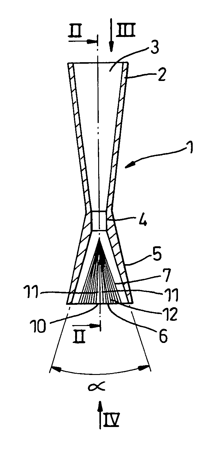
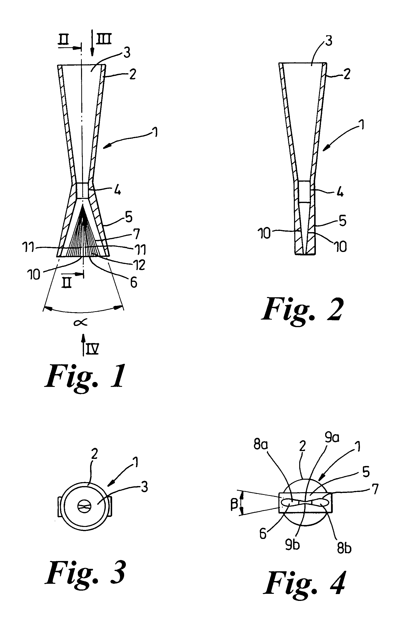
[0026] With reference to FIGS. 1 to 4, a blasting nozzle 1 according to the invention comprises an inlet 2 for attachment to an outlet hose (not shown) of a conventional blasting apparatus, for example such as that described in WO 03 / 045633. The inlet 2 can be made in any appropriate shape for attachment to the apparatus but typically simply comprises a tubular portion with a circular orifice 3. Downstream of the inlet 2 is an accelerating portion 4 that, as in conventional nozzles, comprises a venturi. The inlet 2 therefore tapers to a short constricted portion prior to commencement of an outlet portion 5 through which an abrasive-laden fluid jet supplied from the blasting apparatus can be ejected and directed onto a surface to be blasted by an operator.

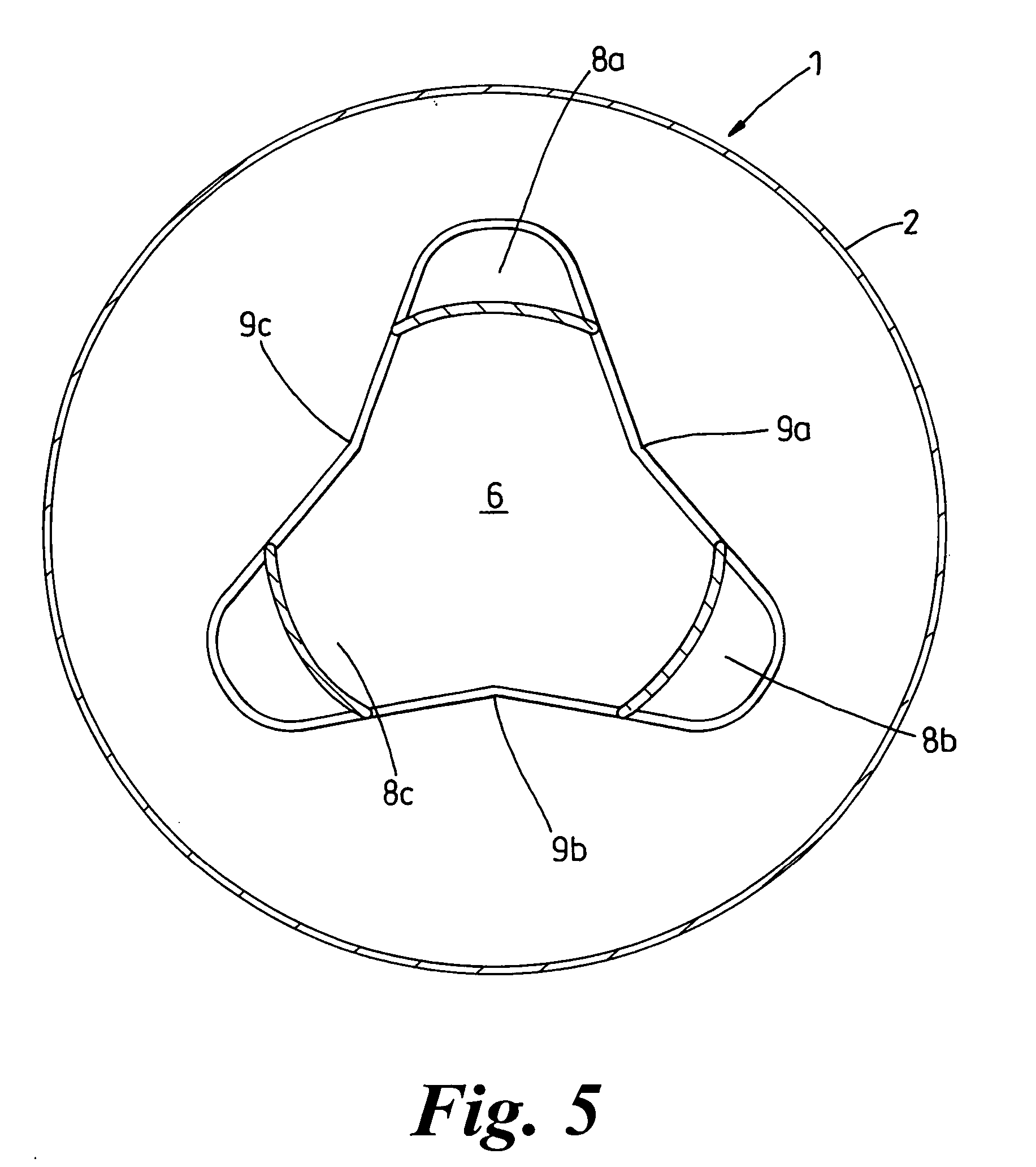
[0027] The outlet portion 5 is defines a single outlet orifice 6 and a single interior surface 7 which is shaped as will now be described to affect the abrasive distribution in the jet. The surface 7 flares from the constricted acce...


PUM


Abstract

A blasting nozzle for a blasting apparatus includes an inlet for attachment to the outlet hose of the blasting apparatus, an accelerating portion, and an outlet portion through which an accelerated abrasive-laden jet can be ejected. The outlet portion has an interior surface that flares outwards to define a single outlet orifice but that also defines a transverse cross-section profile having at least two lobes between which is at least one splitter element. In use, the abrasive within the jet is directed by the splitter element into one or other of the two lobes within the single egressing jet. The overall effect is such that the abrasive distribution transversely across the jet is much more even than in a conventional blasting nozzle.

Description

RELATED U.S. APPLICATIONS [0001] Not applicable. STATEMENT REGARDING FEDERALLY SPONSORED RESEARCH OR DEVELOPMENT [0002] Not applicable. REFERENCE TO MICROFICHE APPENDIX [0003] Not applicable. FIELD OF THE INVENTION [0004] The present invention relates to a blasting nozzle primarily for use in an abrasive blasting apparatus and, in particular, in a dustless abrasive blasting apparatus. However, the nozzle is also suitable for use in water jetting and in wet and dry abrasive blasting. BACKGROUND OF THE INVENTION [0005] In dustless abrasive blasting, an abrasive is entrained in a pressurized fluid flow or gaseous-entrained liquid flow and is directed against the surface to be treated by a controllable nozzle. It is the intention of such apparatus to coat each particle of the abrasive with the liquid so that the abrasive is weighted by the liquid and falls safely to the ground after striking the surface to be blasted, generally obviating the requirement for the operator of the apparatus...

Claims


Application Information

Patent Timeline
Patent Type & Authority Applications(United States)
IPC IPC(8): B24C5/04B05B1/04
CPCB24C5/04B05B1/04B05B1/042B05B1/044
Inventor DORE, DAVID JAMES
Owner QUILL INTERNATIONAL INDUSTRIES PLC
Why Eureka
Try Eureka