Quality control of the frit for OLED sealing

a technology of quality control and frit, which is applied in the field of quality control of frit for oled sealing, can solve the problems of difficult development of sealing process, oled display, and organic layer located therein susceptible to degradation, and achieve the effects of improving process control, good quality and quantity of information, and reducing defects

Inactive Publication Date: 2010-05-13
CORNING INC
View PDF9 Cites 35 Cited by
  • Summary
  • Abstract
  • Description
  • Claims
  • Application Information

AI Technical Summary

Benefits of technology

[0021]This disclosure shows that good quality and quantity of information can be obtained from the thermal detector during or before an OLED sealing process. This leads to improved process control thereby leading to lower levels of defects. Also achieved is good accuracy of predicting hermeticity failures based on the thermal signatures. Also, by detecting defects at the seal and providing appropriate feedback immediately to upstream processes, significant cost savings could be realized in production settings.

Problems solved by technology

However, OLED displays and, in particular, the electrodes and organic layers located therein are susceptible to degradation resulting from interaction with oxygen and moisture leaking into the OLED display from the ambient environment.
Unfortunately, in the past it has been very difficult to develop a sealing process to hermetically seal the OLED display.
Historically, epoxies have been used to hermetically seal the displays but moisture still permeates the seal to shorten life.
The dispensing of the frit on the cover glass for OLED sealing occasionally suffers from the presence of defects such as high spots, voids and thickness variations.
These types of defects may create sealing defects leading to failure of the product.
The overall process suffers from low yield due to the presence of defects.
A significant amount of work has been done to improve the quality of dispensing but sealing yields are still a problem.
The topography of the dispensed frit can be monitored with a low coherency interferometer or optical microscope, but these are very slow or expensive processes.

Method used


Image

  • Quality control of the frit for OLED sealing
  • Quality control of the frit for OLED sealing
  • Quality control of the frit for OLED sealing

Examples


example 1

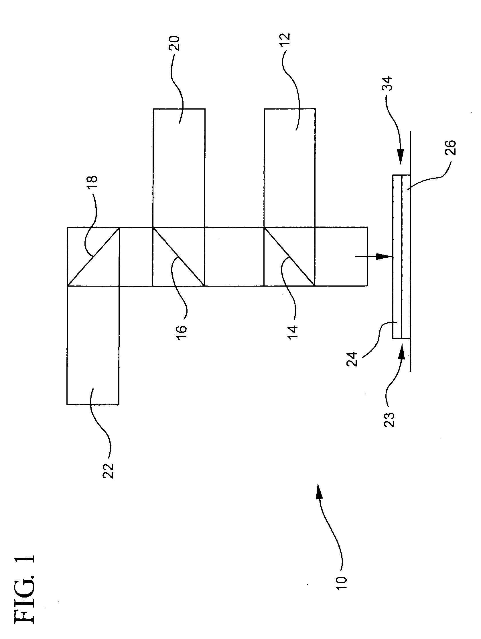
[0051]FIG. 3A shows a typical temperature profile using a thermo-detector on a laser sealing head described above as generally shown in FIG. 1. For this and the other examples, the laser power was 27-30 W and the laser beam was moved around the frit frame lines at a speed of 50 mm / sec. The frit frame lines were pre-sintered onto the cover display glass (heating from room temperature to about 450° C.). The frit on the cover glass sheet was sintered to the substrate display glass sheet by laser sealing. Both the cover sheet and substrate glass sheet were Corning Eagle XG® glass. The substrate had no OLED displays formed on it.

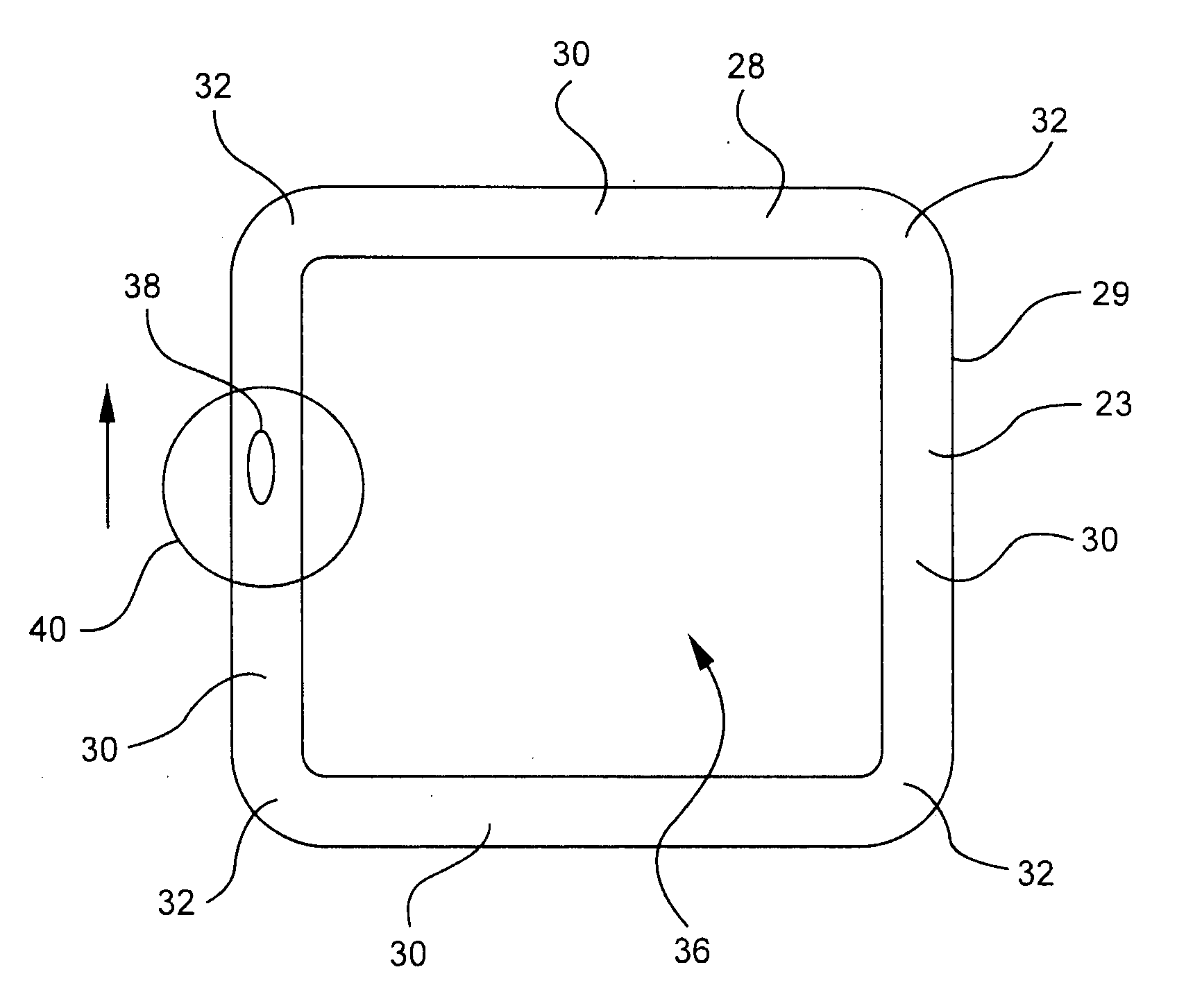
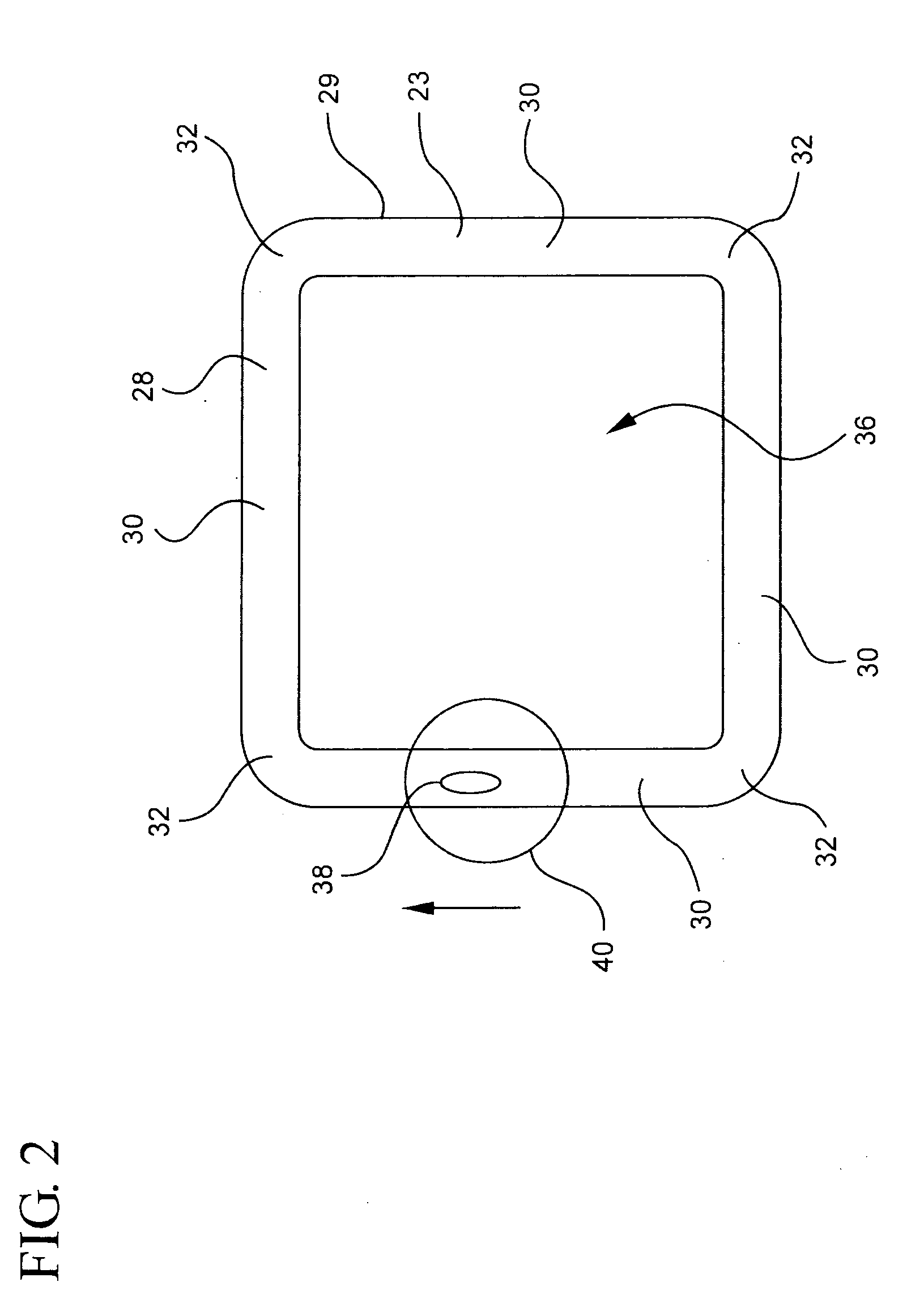
[0052]FIG. 3B shows the direction of frit dispensing from a micropen dispenser: in the clockwise direction from the dispenser start to the dispenser stop position (dispenser start-stop, DSS). The laser was moved during sealing and thermal detection from the laser start to the laser stop position (laser start stop, LSS). While traveling around the cell, the laser ...

example 2

[0053]FIG. 4 shows the results of a correlation study between a signature temperature spike (high and narrow peak) and surface contamination on the frit line. The glass surface contaminant leads to different laser energy absorption. Here, the temperature spike was a signature for a defect. The surface contamination on the glass was so bad that the laser light did not fully reach the frit, resulting in a peak in temperature. Normally, as was the case here, a temperature spike results from glass surface contamination and does not represent a frit line defect.

example 3

[0054]FIGS. 5A and 5B correlate temperature peaks and damaged frit lines. Temperature changes were seen in the thermal profiles of FIGS. 5A and 5B. The presence of a temperature spike (circled) is normally not determinative of whether there is a frit defect. In this rare situation, however, the surface defect of the glass (seen as a smear or scratch) was so severe that the laser light was blocked from reaching the frit and a frit line defect resulted.

[0055]FIG. 5B was an example of a glass surface defect and a minimal thermal response. The smear on the cover glass that was located on the cell that produced the thermal signature of FIG. 5A was actually also located on the cell that produced the thermal signature of FIG. 5B. Here, the smear and the minimal frit line damage to the cell were observed by the optical microscope first. This frit line damage did not impact OLED display performance. Next, the thermal response curve was analyzed (FIG. 5B), showing a peak (circled) that was so...


PUM

PropertyMeasurementUnit
thickaaaaaaaaaa
thickaaaaaaaaaa
temperatureaaaaaaaaaa

Abstract

A method of finding defects in sealing material formed as a frame line on a glass plate includes irradiating the frame line of sealing material. A temperature of the irradiated sealing material is measured and a change of the temperature caused by a nonuniformity in sealing material is detected. Another aspect features a method of hermetically sealing a thin film device between glass plates. Sealing material is dispensed on a cover glass plate in the form of a frame line cell. The sealing material is pre-sintered onto the cover glass plate and cooled. A laser beam is moved around the frame line on the sealing material. A temperature of the sealing material contacted with the laser beam is measured. A change in the temperature (ΔT) caused by a nonuniformity in the sealing material is measured. Further aspects include a feedback process, infrared imaging and use of delta temperature data to increase sensitivity of temperature measurement data.

Description

TECHNICAL FIELD[0001]The present disclosure is directed to a process for detecting defects in sealing material used for hermetically sealing thin film devices (e.g., OLED devices) between glass plates.TECHNICAL BACKGROUND[0002]OLEDs (organic light emitting diodes) have been the subject of considerable research in recent years because of their use in a wide variety of electroluminescent devices, including GPS units, cell phones, cameras and televisions. A single OLED can be used in a discrete light emitting device or an array of OLEDs can be used in lighting applications or flat panel display applications (e.g., OLED displays). OLEDs are solid state devices made of thin organic molecules that create light with the application of electricity. Primary advantages of these devices are a crisper, brighter display than an LCD that also uses less power. OLED displays are known to be very bright and to have a good color contrast and wide viewing angle. However, OLED displays and, in particul...

Claims


Application Information

Patent Timeline
Patent Type & Authority Applications(United States)
IPC IPC(8): G01N25/18
CPCH01L51/5246G01N25/72H10K50/8426
Inventor LAI, CHANGYILOGUNOV, STEPHAN LVOVICHLOREY, JOHN DAVIDSCHNEIDER, VITOR MARINO
Owner CORNING INC
Why Eureka
Try Eureka