Biopsy needle

a needle and biopsy technology, applied in the field of biopsy needles, can solve problems such as trauma to patients

Inactive Publication Date: 2006-03-23
MILLER STUART H
View PDF7 Cites 19 Cited by
  • Summary
  • Abstract
  • Description
  • Claims
  • Application Information

AI Technical Summary

Problems solved by technology

Biopsy sample collection using this “brute force” approach results in trauma to the patient.

Method used


Image

  • Biopsy needle
  • Biopsy needle
  • Biopsy needle

Examples


Embodiment Construction

[0023] The detailed embodiments of the present invention are disclosed herein. It should be understood, however, that the disclosed embodiments are merely exemplary of the invention, which may be embodied in various forms. Therefore, the details disclosed herein are not to be interpreted as limiting, but merely as the basis for the claims and as a basis for teaching one skilled in the art how to make and / or use the invention.

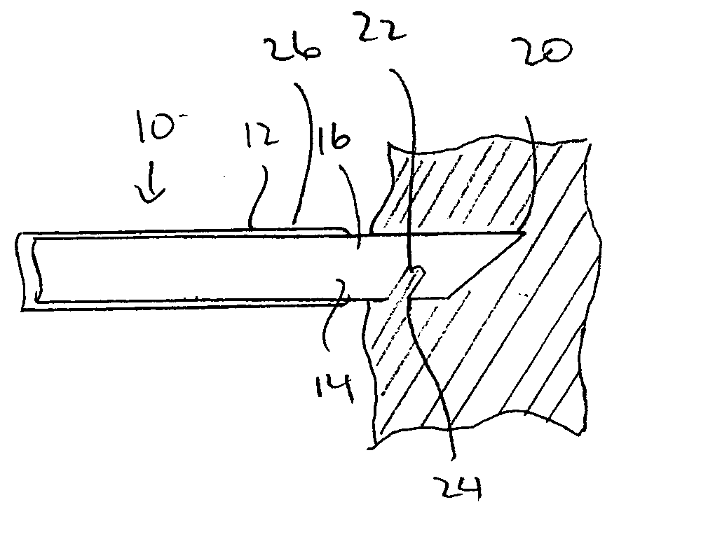
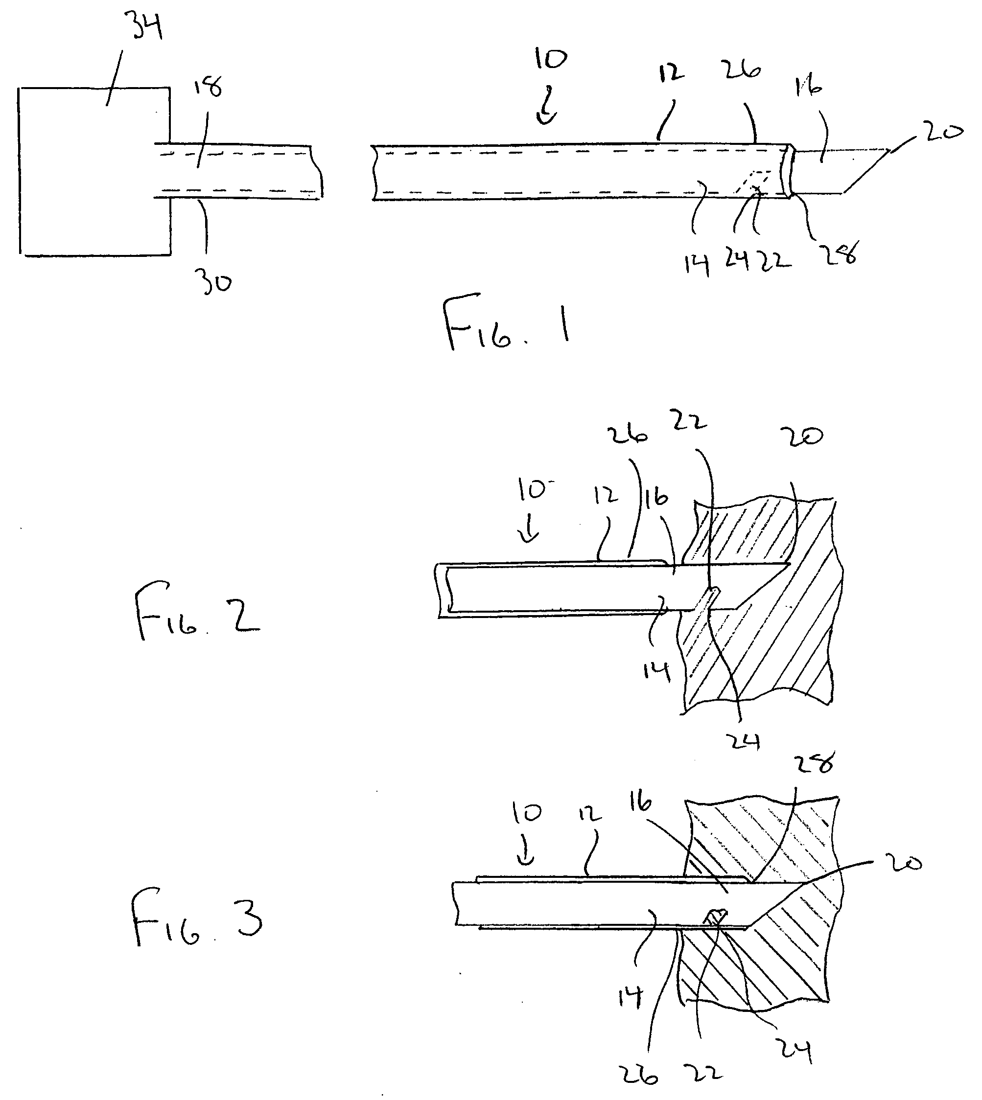
[0024] With reference to FIGS. 1 through 7, a biopsy needle 10 in accordance with the present invention is disclosed. The biopsy needle 10 generally includes a cutting outer cannula 12 that surrounds a solid inner cannula 14. As those skilled in the art will certainly appreciate, the cutting outer cannula 12 is shaped and dimensioned to fit about the inner cannula 14 in a manner permitting relative movement with the removal of core biopsy samples upon proper actuation of the biopsy needle 10. With this in mind, the outer cannula 12 fits closely about the inner ...


PUM


Abstract

A biopsy needle includes an outer cannula and an inner cannula. The inner cannula includes a distal end and a proximal end. The outer cannula is shaped and dimensioned to closely circumscribe the inner cannula for movement relative thereto. The inner cannula further includes a sample recess at its distal end, the sample recess including a U-shaped cutting edge defined bypn=xn cos θqn=xn sin θwhere, θ is an angle at which the cutting edge is formed. xn is an actual length position along the sample recess, pn is a length position of the sample recess relative to the cutting edge along a line substantially parallel to an inner cannula longitudinal axis, and qn is a depth position of the sample recess relative to an apex of an arc defined by a cutting edge.

Description

CROSS REFERENCE TO RELATED APPLICATIONS [0001] This application is based upon U.S. Provisional Application Ser. No. 60 / 610,542, entitled “BIOPSY NEEDLE”, which was filed Sep. 17, 2004.BACKGROUND OF THE INVENTION [0002] 1. Field of the Invention [0003] The invention relates to a biopsy needle. More particularly, the invention relates to a biopsy needle having a sample recess shaped and dimensioned to optimize operation of the biopsy needle. The invention also relates to a method for forming the recess. [0004] 2. Description of the Prior Art [0005] Biopsy needles are currently available in gages ranging from 14 to 20. The biopsy samples are obtained using various methods. One of the commercially available designs employs a solid, pointed cannula inside of a slip-fitted outer cannula with a beveled leading end. The solid inner cannula contains a rectangular cavity, which collects the biopsy sample. The biopsy sample is removed from the tissue by inserting the biopsy needle into the tis...

Claims


Application Information

Patent Timeline
Patent Type & Authority Applications(United States)
IPC IPC(8): A61B10/00
CPCA61B10/0275
Inventor MILLER, STUART H.
Owner MILLER STUART H
Why Eureka
Try Eureka