Guiding catheter with embolic protection by proximal occlusion

a guiding catheter and proximal occlusion technology, applied in balloon catheters, surgery, other medical devices, etc., can solve the problems of complex use of multi-catheter systems used to form isolated treatment chambers, cumbersome system preparation and use, etc., and achieve stable and secure position

Inactive Publication Date: 2006-03-23
MEDTRONIC VASCULAR INC
View PDF19 Cites 40 Cited by
  • Summary
  • Abstract
  • Description
  • Claims
  • Application Information

AI Technical Summary

Benefits of technology

[0009] In other embodiments of the invention, one or more steering wires may be slidably disposed in dedicated lumens within the guiding catheter, the steering wires being fixed to the catheter distal end. The guiding catheter may also include an actuation assembly having one or more steering actuation reels connected to the steering wires. Tension applied to the steering wire(s) causes deflection in a distal region of the guiding catheter, thus deforming the relatively straight or pre-curved shape of the catheter. The deformed shape may assist in “steering” the guiding catheter through a patient's vasculature, or the altered shape may provide a more stable, secure position during advancement of therapeutic devices, as when forcing a deflated angioplasty balloon through a tight stenosis, for example.

Problems solved by technology

Known occluder devices typically employ an inflatable occlusion balloon with its attendant expansion apparatuses, which may make the system cumbersome to prepare and use.
Additionally, multi-catheter systems used to form isolated treatment chambers may be complex to use when it is desirable for the physician to work quickly to minimize the duration of hemostasis.

Method used


Image

  • Guiding catheter with embolic protection by proximal occlusion
  • Guiding catheter with embolic protection by proximal occlusion
  • Guiding catheter with embolic protection by proximal occlusion

Examples


Embodiment Construction

[0024] The following detailed description is merely exemplary in nature and is not intended to limit the invention or the application and uses of the invention. Although the description of the invention is in the context of protection against atheroembolization during treatment of blood vessels such as the coronary, carotid and renal arteries, the invention may also be used in any other passageways where it is deemed useful to provide temporary occlusion to block fluid flow. Furthermore, there is no intention to be bound by any expressed or implied theory presented in the preceding technical field, background, brief summary or the following detailed description.

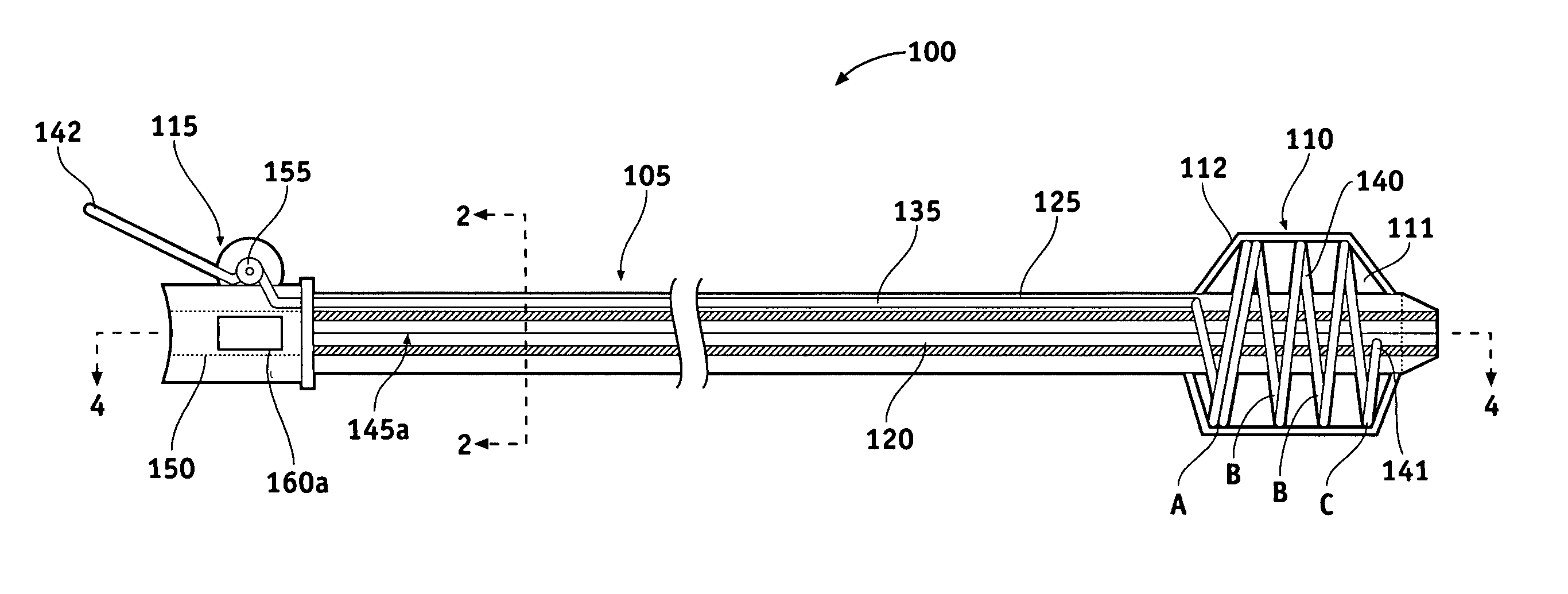
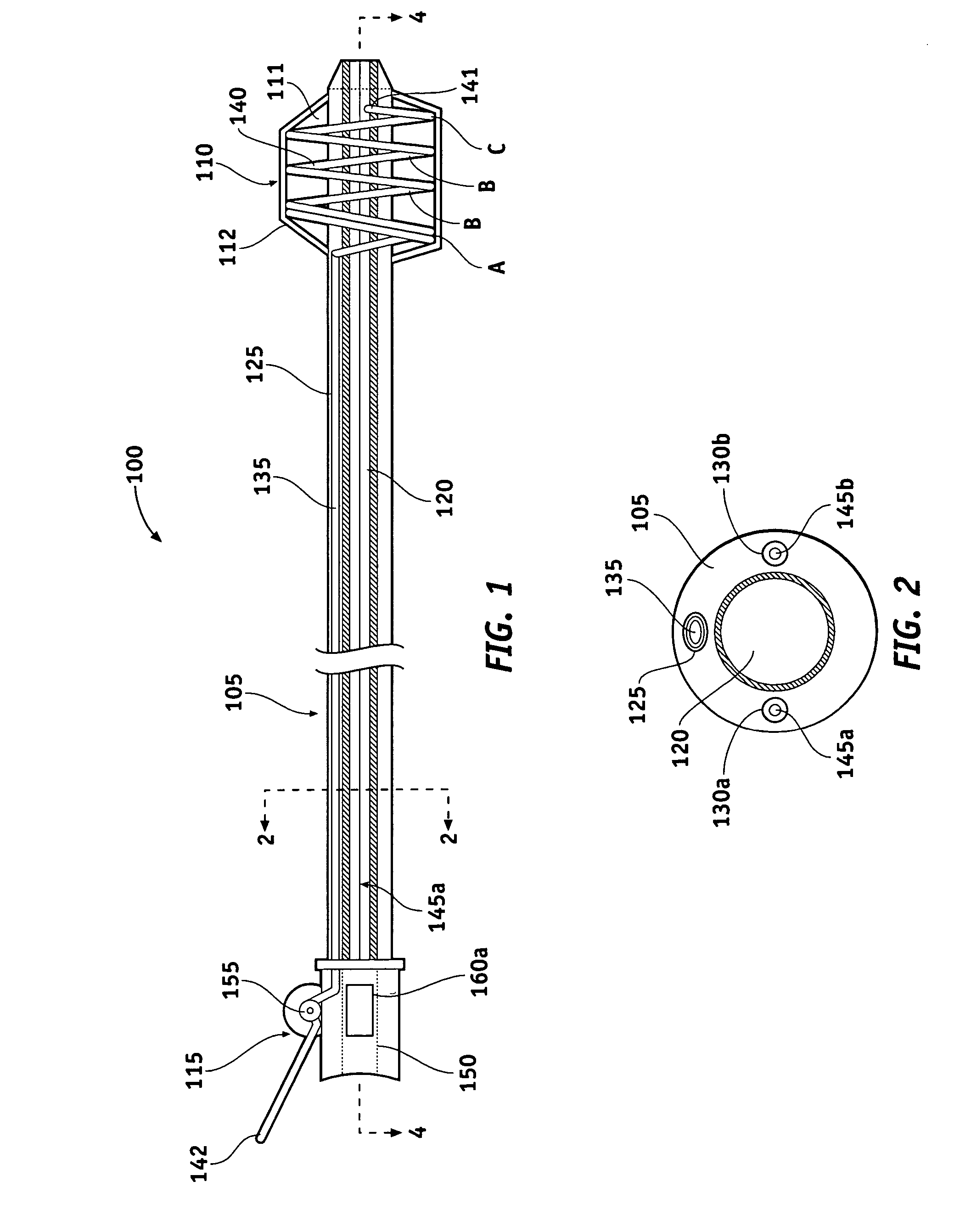
[0025]FIG. 1 is a longitudinal cross-sectional view showing one embodiment of a guiding catheter 100 in a deployed condition, and FIG. 2 shows a cross-sectional view taken along line 2-2 of FIG. 1. Guiding catheter 100 includes catheter shaft 105, sealing member 110 adjacent a distal end of the catheter shaft and actuation a...


PUM


Abstract

A guiding catheter includes an elongate shaft with a central lumen and a mechanically expandable sealing membrane mounted about the distal end of the shaft. An expansion wire is slidably disposed in a dedicated lumen within the catheter, the expansion wire having an expandable distal portion with a pre-formed expanded shape capable of expanding the sealing membrane into sealing engagement with the wall of an artery to provide occlusion of blood flowing through the artery. In one embodiment, a steering wire is slidably disposed in a dedicated lumen within the catheter and is fixed adjacent the shaft distal end. Pushing or pulling the steering wire deflects the distal end of the catheter. In another embodiment, the guiding catheter has a pre-formed curve adjacent the distal end of the shaft.

Description

FIELD OF THE INVENTION [0001] The present invention relates generally to an intraluminal guiding catheter used in a medical procedure, and more particularly, to a guiding catheter with embolic protection by proximal occlusion. BACKGROUND OF THE INVENTION [0002] Stenosis, or narrowing of a blood vessel such as a coronary artery may comprise a hard, calcified substance and / or a softer thrombus material. There have been numerous therapeutic procedures developed for the treatment of stenosis in a coronary artery. One of the better-known procedures is percutaneous transluminal coronary angioplasty (PTCA). According to this procedure, the narrowing in the artery can be reduced by positioning a dilatation balloon across the stenosis and inflating the balloon to re-establish acceptable blood flow through the artery. Additional therapeutic procedures may include stent deployment, atherectomy, and thrombectomy, which are well known and have proven effective in the treatment of such stenotic l...

Claims


Application Information

Patent Timeline
Patent Type & Authority Applications(United States)
IPC IPC(8): A61M29/00
CPCA61M25/0068A61M25/0074A61M25/0082A61M25/0147A61M25/0152A61M2025/1068A61M29/02A61M2025/0079A61M2025/0081A61M2025/1052A61M25/04
Inventor COYLE, JAMES
Owner MEDTRONIC VASCULAR INC
Why Eureka
Try Eureka