Locking screw for an intramedullary nail

a locking screw and intramedullary technology, applied in the field of orthopaedic implants, can solve the problems of preventing or reducing the success rate of healing, and affecting the healing effect of the nail

Active Publication Date: 2006-03-23
DEPUY SYNTHES PROD INC +1
View PDF74 Cites 156 Cited by
  • Summary
  • Abstract
  • Description
  • Claims
  • Application Information

AI Technical Summary

Benefits of technology

[0019] Alternatively, the longitudinal wedging element may have a cross-sectional profile, which corresponds to the cross-sectional profile of the passage and preferably is constructed wedge-shaped. The passage may be essentially circular with a diameter of 0.5-2.0 mm and preferably of 0.8-1.2 mm. The longitudinal wedging element typically has a length, which corresponds to at least two thirds of the shaft of the screw. At one of its ends, the longitudinal wedging element may have a stop for the head of the screw. With that, the wedging element is prevented from piercing through the passage.

Problems solved by technology

In both cases, a certain targeting inaccuracy is unavoidable, that is, the tip of the screw cannot be aligned exactly coaxially with the middle axis of the transverse borehole and, instead, deviates therefrom by a certain amount.
However, because of the underdimensioning, there is a certain clearance between the locking screw and the transverse borehole.
Together with the flexibility of the material and of the overall device, this may cumulatively assume a magnitude, which prevents successful healing or delays it significantly.
Admittedly, this clearance is unavoidable in order to guarantee the applicability of the locking for the surgeon.
However, it is clinically undesirable for certain indications, such as metaphysical fragments.

Method used


Image

  • Locking screw for an intramedullary nail
  • Locking screw for an intramedullary nail
  • Locking screw for an intramedullary nail

Examples


Embodiment Construction

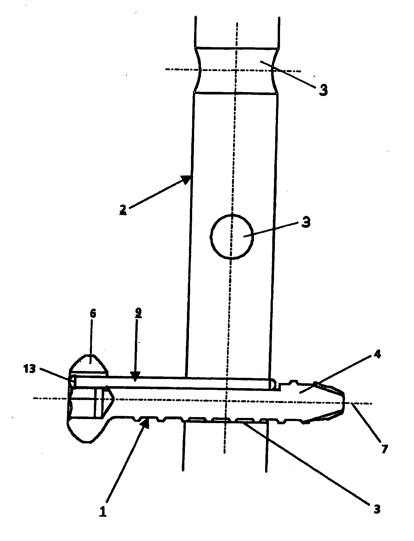
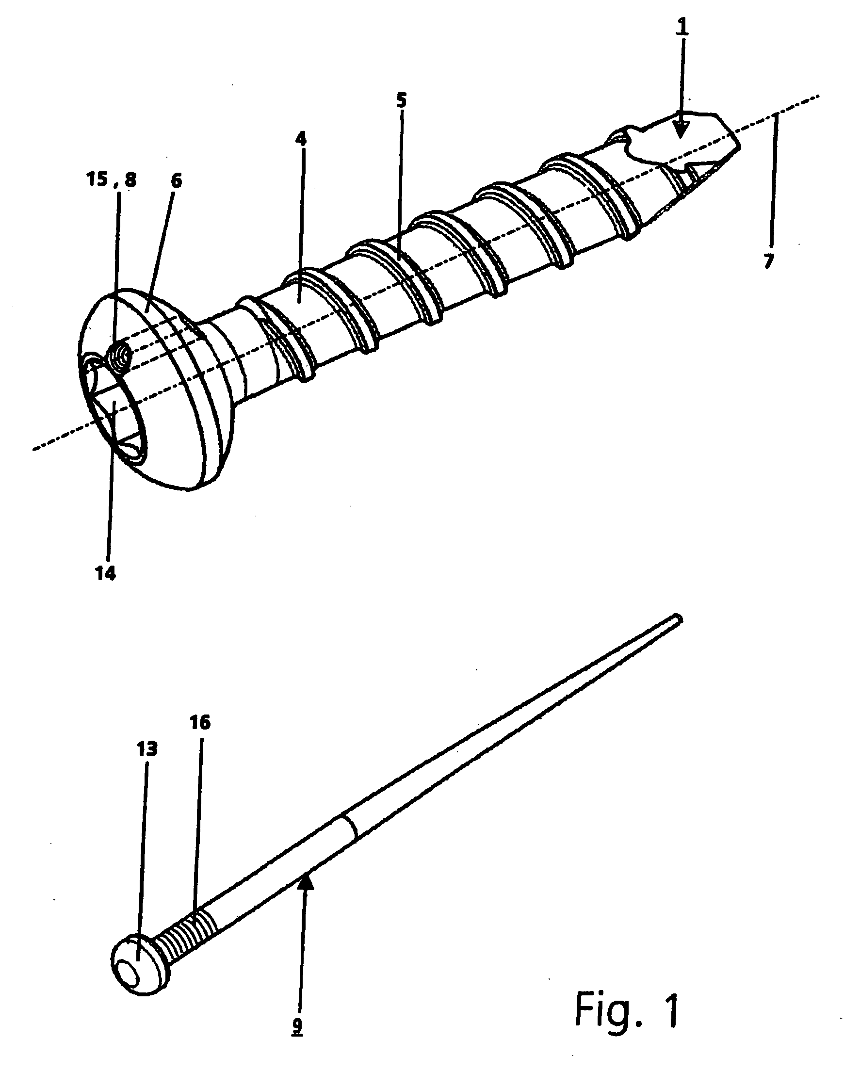
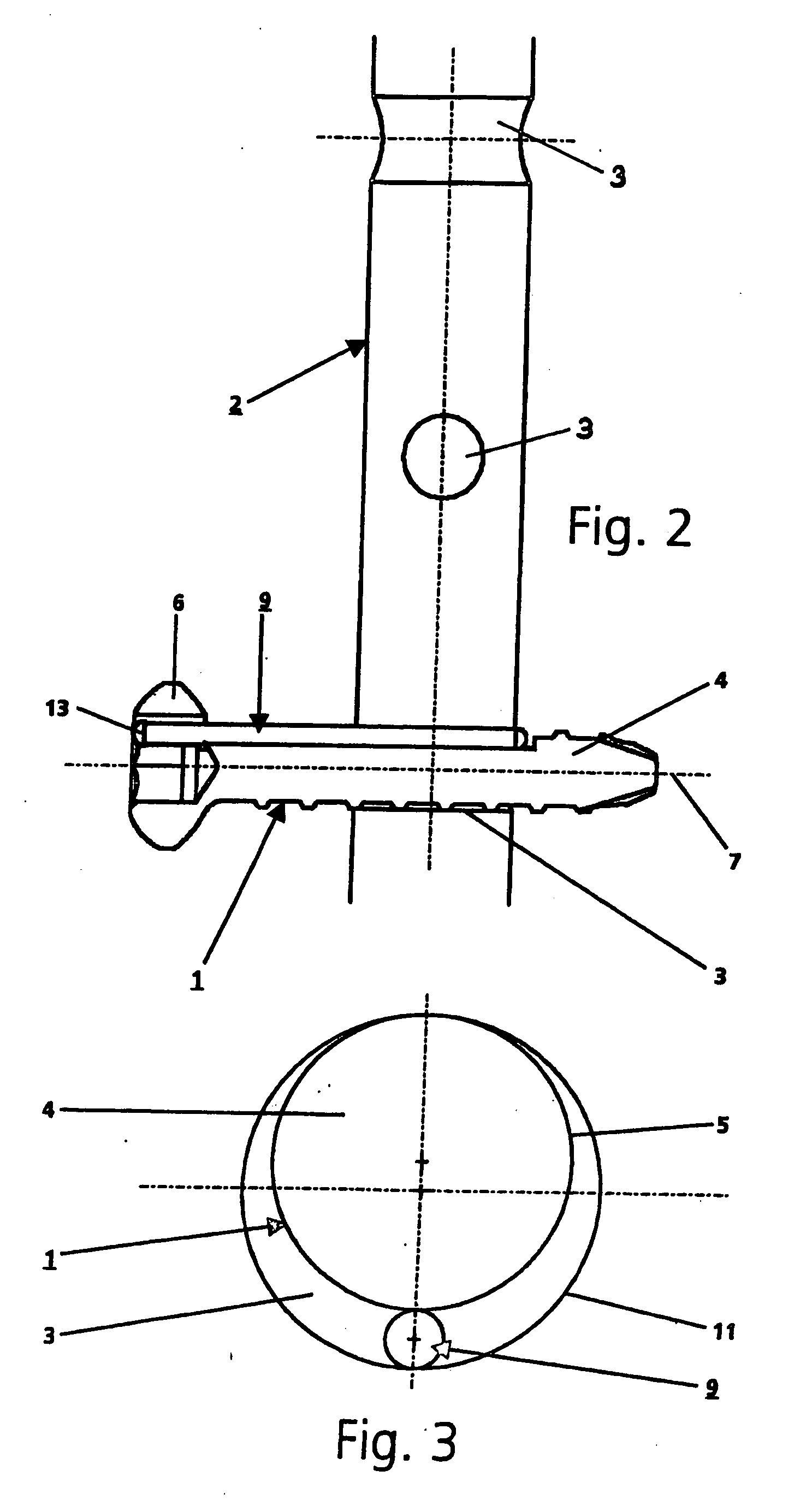
[0034] The locking screw 1, shown in FIG. 1, is used for locking an intramedullary nail 2, which is shown in FIG. 2 and has several transverse boreholes 3. The locking screw 1 has a central longitudinal axis 7 and comprises a screw shaft 4, which is provided with an external thread 5, as well as a screw head 6, with a hexagonal socket 14, in order to be able to turn the locking screw 1 in one of the transverse boreholes 3 of the intramedullary nail 2.

[0035] The diameter of the screw head 6 is larger than the external diameter of the external thread 5, the screw head 6 having a passage 8 in the form of a circular borehole, which extends essentially parallel to the longitudinal axis 7 and to the external thread 5 and has an internal thread 15 for accommodating a longitudinal wedging element 9 in the form of a conically extending nail with a partial external thread 16 and a stop 13 at the head, the external thread 16 corresponding to the internal thread 15. The wedging element 9 has a...


PUM


Abstract

A locking screw for an intramedullary nail having at least one transverse hole. The locking screw has a central longitudinal axis and includes a screw shank, which is at least partially provided with an external thread, and a screw head. The diameter of the screw head is greater than the outer diameter of the external thread, and the screw head includes a passage extending generally parallel to the longitudinal axis of the screw and the external thread. The passage is configured to receive a longitudinal wedge element. As a result, any gap between the locking screw and the intramedullary nail is eliminated and the screw is wedged in position in the transverse hole of the intramedullary nail.

Description

RELATED APPLICATION DATA [0001] The present application is a continuation of the U.S. National Stage designation of co-pending International Patent Application No. PCT / CH2003 / 000157, filed Mar. 7, 2003, the entire content of which is expressly incorporated herein by reference thereto.FIELD OF THE INVENTION [0002] The present invention relates to orthopaedic implants and, more particularly, to a locking screw for use with an intramedullary nail, wherein the screw includes a head portion with a passage for receiving a longitudinal wedge element. BACKGROUND OF THE INVENTION [0003] The locking of intramedullary nails is known in the art, e.g., locking screws are introduced into the transverse boreholes of the intramedullary nail either with the help of an imaging method (X-ray control) or a fairly complicated targeting device. In both cases, a certain targeting inaccuracy is unavoidable, that is, the tip of the screw cannot be aligned exactly coaxially with the middle axis of the transv...

Claims


Application Information

Patent Timeline
Patent Type & Authority Applications(United States)
IPC IPC(8): A61B17/56A61B17/70A61B17/72A61B17/86
CPCA61B2017/8655A61B17/725A61B17/70A61B17/72
Inventor SENN, PETERSCHLIENGER, ANDREBUETTLER, MARKUS
Owner DEPUY SYNTHES PROD INC
Why Eureka
Try Eureka