Load cells for use in high precision load measuring system

a load cell and high-precision technology, applied in the field of vehicle load weighing systems, can solve the problems of system insufficient accuracy or precision, analog signal that represents weight is subject to loss and noise, and cannot be used for customer billing, etc., to achieve the effect of reducing the deleterious effects of mechanical and electrical noise on the measured weigh

Inactive Publication Date: 2006-03-23
THE AIS GROUP
View PDF15 Cites 17 Cited by
  • Summary
  • Abstract
  • Description
  • Claims
  • Application Information

AI Technical Summary

Benefits of technology

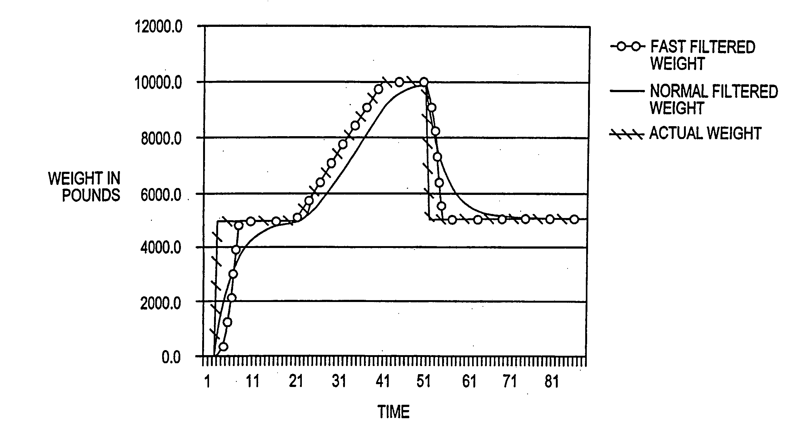
[0012] Another object of the invention is to improve the accuracy of a load cell by using sophisticated formulas or piecewise linearization for temperature compensation and linearity compensation to better convert raw strain gauge readings into weight readings.
[0053] Another embodiment of the present invention is a method of enhancing environmental conservation through encouraging recycling through the use of variable pricing for waste pick-ups. General unsorted waste would be priced at a commercial rate. Segregated scrap, such as iron, copper, brass, paper and other such recyclable material would be picked up for free or at a greatly reduced rate. Through the incentive pricing, consumers and businesses would be encouraged to separate recyclable materials. Pricing policies could be implemented that provide rebates to customers who segregated commercially viable amounts of particularly valuable recyclable materials. Because quantities of unsorted garbage and recyclable materials can be measured accurately, with the on-board load weighing system, and records can be accurately kept on the Cab display controller, the method can be implemented without the need for costly and time consuming external scales.

Problems solved by technology

These systems were not used for customer billing because these systems did not have sufficient accuracy or precision.
One problem with junction box systems is that the analog signal that represents weight is subject to loss and noise between the load cell and the junction box.
This limits the accuracy that can be achieved with these systems.
The limited error correction that these systems are capable of performing does not enable these systems to be of sufficient accuracy for customer billing.
The system, however, uses the pressure of air in the air suspension for the trailer and does not use high precision load cells.
These prior art systems suffer from lack of accuracy and lack of resolution needed to maintain accurate customer billings.
These systems are also susceptible to mechanical and electrical noise causing weight measurements to be degraded.
Measurement drift due to temperature changes and creep of the strain gauge over time also degrades results.
Prior art on-board load weighing systems have not been certified or certifiable by weights and measures agencies because they were not sufficiently accurate for customer billing.

Method used


Image

  • Load cells for use in high precision load measuring system
  • Load cells for use in high precision load measuring system
  • Load cells for use in high precision load measuring system

Examples


first embodiment

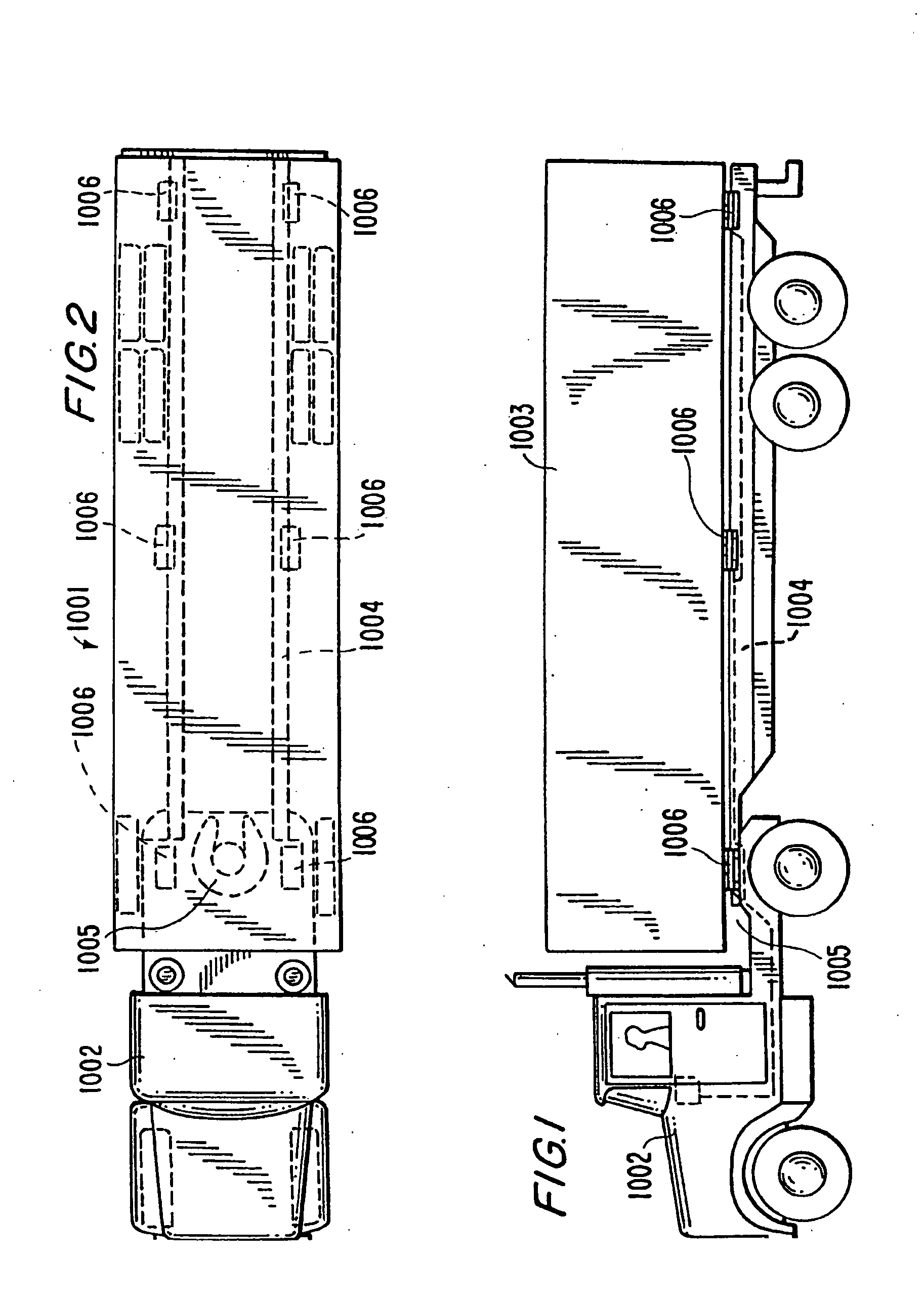
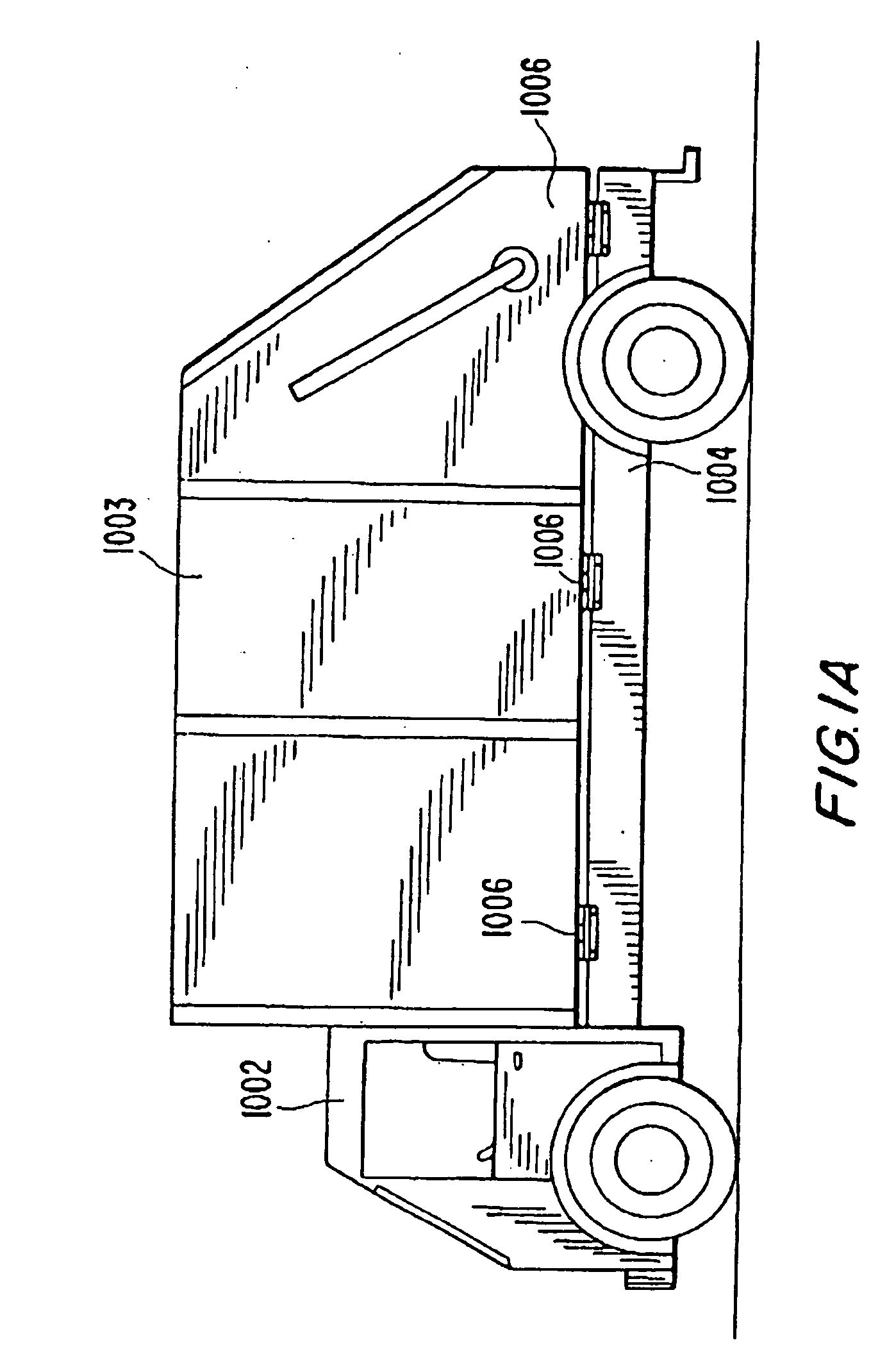
[0089] The mounting arrangement of a typical load cell of the first embodiment is summarized as follows and described in detail thereafter. FIG. 3B shows schematically how an elongated load cell 1006 is situated with its ends upon longitudinally spaced right angle support brackets or coupling means 1010A and 1010B. The load cell's top surface midway between these support brackets is engaged by the bottom 1025A of block or coupling means 1025 welded to the bottom of container 1003. From this arrangement there is a downward force F1 at the center and upward reaction forces F2 and F3 at the supports 1010A and 1010B respectively. Midway between forces F1 and F2 is a set 1051 of strain gauges, and midway between forces F1 and F3 is an identical set 1051 of strain gauges. Each set of strain gauges is adhered to the back wall of a recess which extends inwardly from the front wall of the load cell block. As explained later, for each recess there is an opposite recess extending inwardly from...

second embodiment

[0098] As seen in FIGS. 9 and 11 of this second embodiment, the center of the load cell block 1006A is fixedly mounted to central bracket 1075 by bolt 1076. In this reversed mode the load cell's central contact area 1029 between the notches 1030 faced downward against the corresponding contact area of central support bracket 1075.

Mounting of Sets of Strain Gauges in the Load Cell

[0099] In each load cell the strain gauges are mounted in sets of four as seen in FIGS. 3, 3A and 9. As shown in FIG. 3A, each load cell has two rectangular recesses 1050 extending horizontally inward. In each recess is situated one set of strain gauges 1051 mounted to a plate 1052. As noted earlier, for each recess extending inwardly on one side of the load cell, there is an identical recess extend inwardly from the opposite side. Both recesses extending inwardly, toward but not reaching the other, because of a central web or internal wall that extends vertically and in the front-to-rear direction. One set...


PUM


Abstract

The present invention relates to a load cell operable with a vehicle having a chassis and a container carried by the chassis, with the load cell supported by the chassis and supporting the container for measuring the weight of the container and any load therein, and to a system having a plurality of these load cells on a vehicle, and to a method of executing weight measurements of loads in a container of a vehicle. The load cell includes a plurality of strain gauges and coupling elements in a floating mount configuration for coupling the load cell to the container and to the chassis in a dual shear beam loading configuration, while limited translational movement is permitted of the load cell relative to the container or the chassis. The load cell also has an electrical interface for receiving analog output data from the strain gauges, adaptively filtering this data and outputting a digital signal representative of the weight of the container and any load therein. This invention permits measurement of incremental loads with sufficient accuracy to permit customer billing based on the measurements.

Description

FIELD OF INVENTION [0001] The present invention relates to weighing loads placed on trucks and other vehicles, and, in particular, to vehicle load weighing systems that are sufficiently accurate to enable haulers to accurately bill customers for incremental loads that are picked up over the course of a day. BACKGROUND OF INVENTION [0002] Load cells have been used in vehicle load weighing systems. Many designs of load cells have been used for detection of overload conditions in trucks for safety reasons. These systems were not used for customer billing because these systems did not have sufficient accuracy or precision. It was only necessary that the accuracy be great enough to detect an unsafe load level. [0003] Known load cells utilize strain gauges which may include Wheatstone bridge arrays of fine wires which change resistance when under strain. Examples of related prior art are seen in U.S. Pat. No. 3,661,220 to Harris; U.S. Pat. No. 3,734,216 to Nordstrom et. al; U.S. Pat. No. ...

Claims


Application Information

Patent Timeline
Patent Type & Authority Applications(United States)
IPC IPC(8): G01G23/01G01G19/12
CPCG01G19/12Y10S177/09G01G23/3735
Inventor POTTEBAUM, JAMES R.INALSINGH, AMAR
Owner THE AIS GROUP
Why Eureka
Try Eureka