Small automatic motion control photographing system

Inactive Publication Date: 2006-03-23
NTT INFRASTRUCTURE NETWORK
View PDF8 Cites 13 Cited by
  • Summary
  • Abstract
  • Description
  • Claims
  • Application Information

AI Technical Summary

Benefits of technology

[0006] In consideration of the above circumstances, an object of the present invention is to provide a compact automatic motion cont

Problems solved by technology

However, the compact automatic motion control photographing device is used while connecting the camera to devices such as the computer and the like, that is, the photographing device has not been designed on a concept of carrying and easily taking photos (see

Method used


Image

  • Small automatic motion control photographing system
  • Small automatic motion control photographing system
  • Small automatic motion control photographing system

Examples


Embodiment Construction

[0026] Hereinbelow, an embodiment of the present invention will be explained with reference to the drawings.

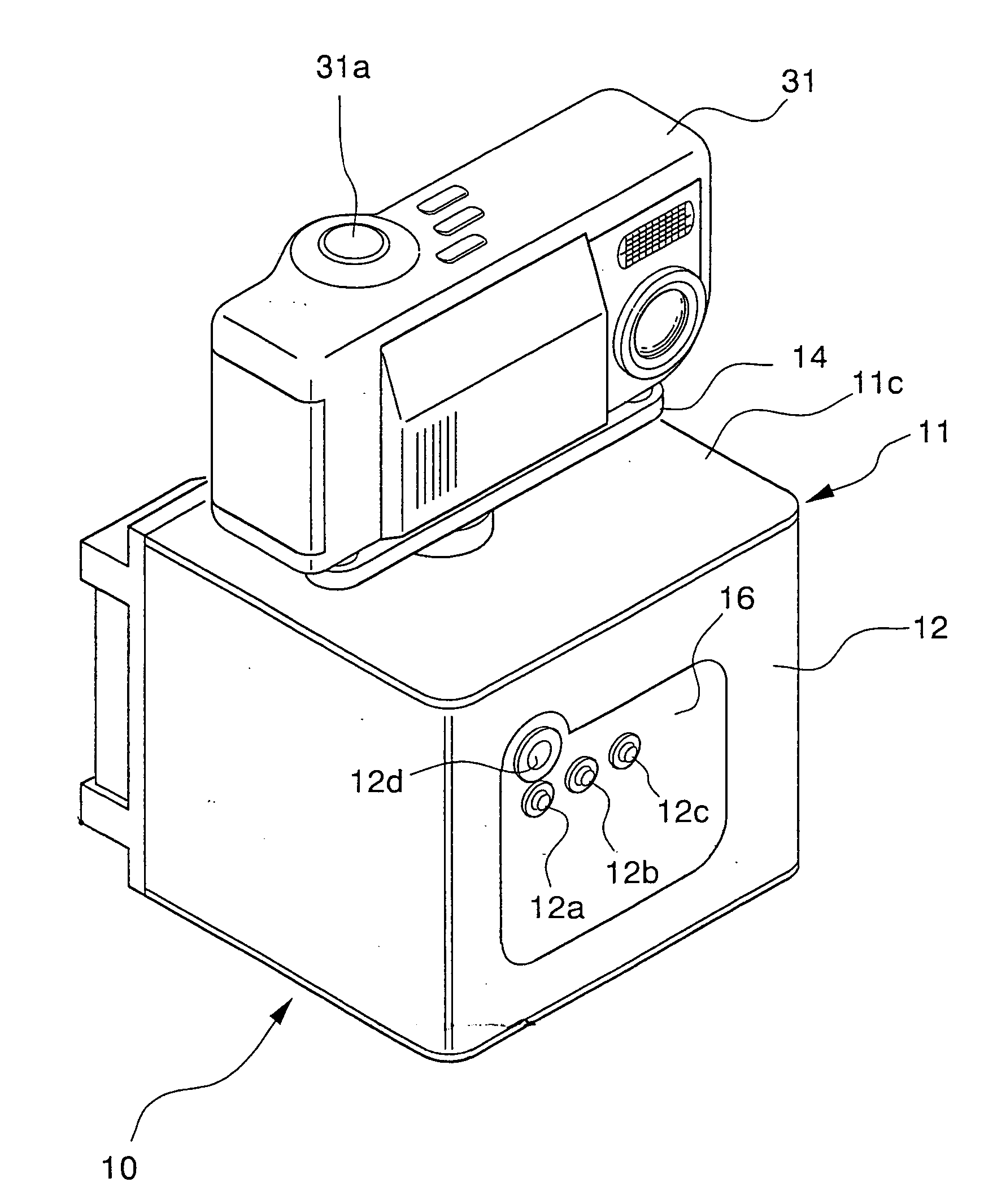
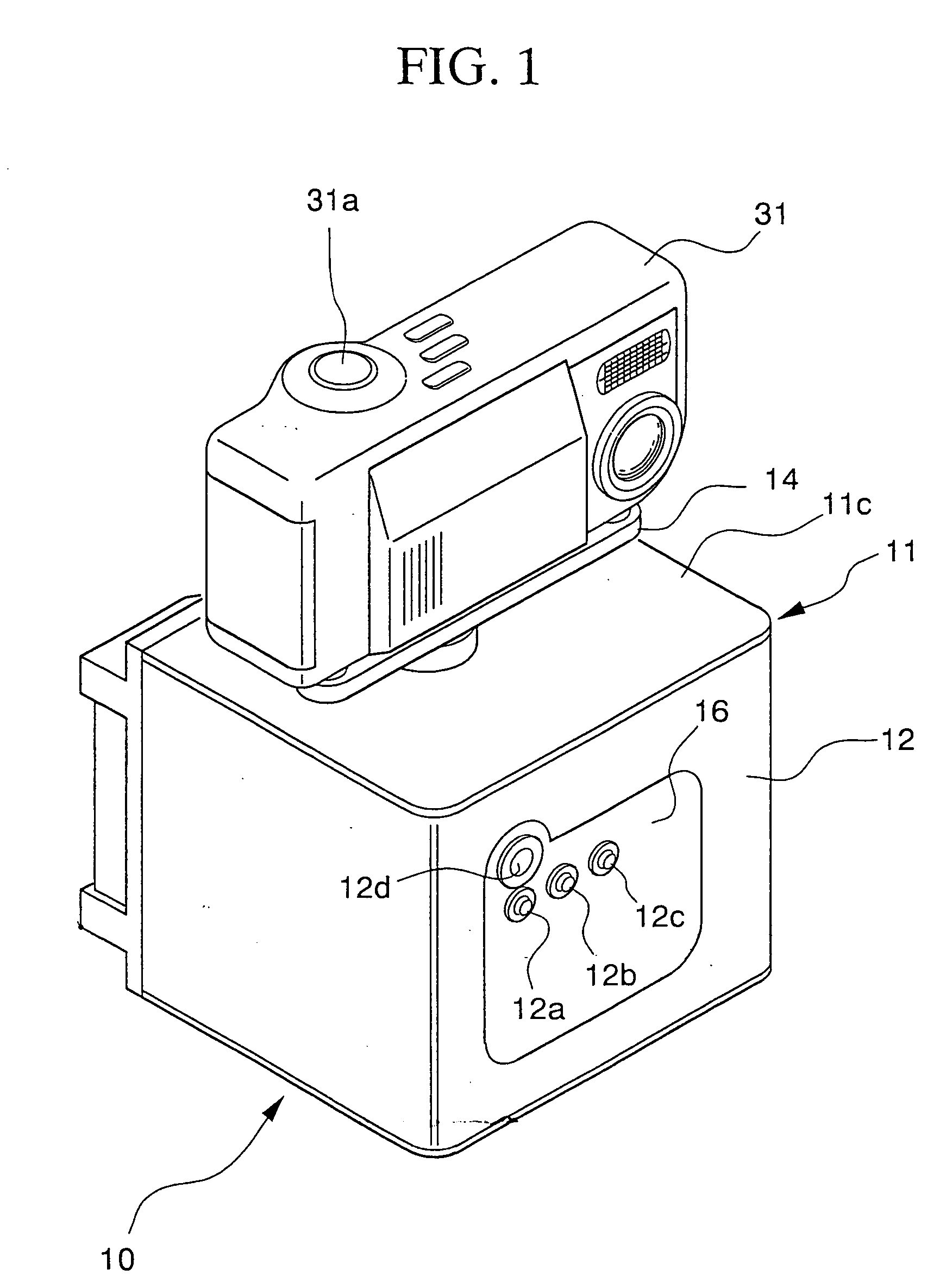
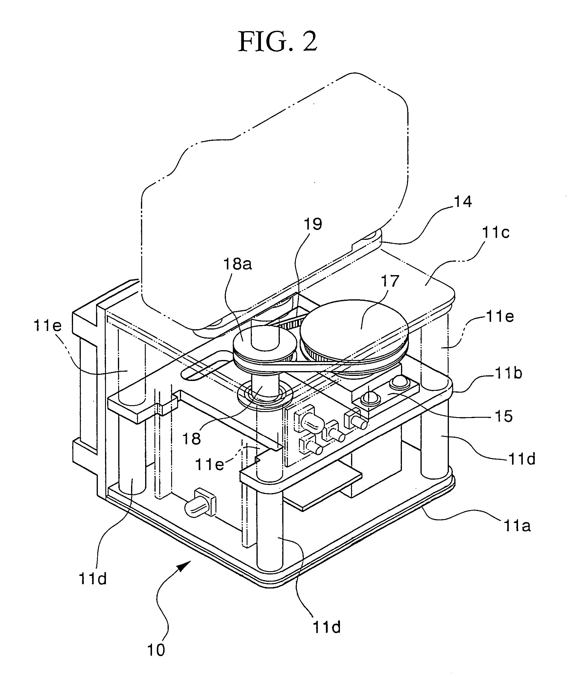
[0027] As shown in FIG. 1, a main body 11 of a compact automatic motion control photographing device 10 has a substantially rectangular parallelepiped shape, and a detachable cover 12 is attached to the front and side faces of the main body. As shown in FIG. 2, a bottom plate 11a, a center plate 11b, and an upper plate 11c, each having a substantially square shape, are respectively provided at the bottom, a center portion, and an upper portion of the main body 11. A plurality of supporting columns 11d are provided between the bottom plate 11a and the center plate 11b, where the columns 11d stand on the bottom plate 11a and support the center plate 11b. A plurality of supporting columns 11e are provided between the center plate 11b and the upper plate 11c, where the columns 11e stand on the center plate 11b and support the upper plate 11c.

[0028] As shown in FIG. 3, a wall 13 ...


PUM


Abstract

A compact automatic motion control photographing device includes a table supported rotatably to at least a single direction; a servo motor for producing a driving force for rotating the table; and a driving force transmitting mechanism for transmitting the driving force produced by the servo motor to the table, wherein the table is rotated towards a single direction and is stopped every time the table has rotated by a predetermined quantity of rotation, so as to perform photographing using a digital camera fastened to the table. Such a compact automatic motion control photographing device has superior portability, by which panoramic photographing can be easily performed by mounting a camera.

Description

TECHNICAL FIELD [0001] The present invention relates to a compact automatic motion control photographing device in which a camera is supported and rotated so as to photograph a panoramic picture. [0002] The present application is based on Japanese Patent Application No. 2003-8257, the content of which is incorporated herein by reference. BACKGROUND ART [0003] In order to take a picture with a wide field of view, that is, a panoramic picture, a series of pictures is taken while rotating the camera in a direction in which the field of view spreads, and the pictures are joined with each other. [0004] A known document discloses a compact automatic motion control photographing device which includes a camera attached to a tripod in a freely rotatable form, a computer for processing image data output from the camera, a CRT display for displaying a panoramic image based on the image processed by the computer, a printer for outputting a hard copy of the panoramic image, and a disk driver for...

Claims


Application Information

Patent Timeline
IPC IPC(8): G01P3/00F16M11/08F16M11/18G03B17/56H04N5/222H04N5/232
CPCF16M11/08F16M11/18H04N5/23238H04N5/232F16M13/00H04N23/60H04N23/698
Inventor SUGIURA, SHINICHIOTSUKI, KAZUHIRONISHIWAKI, KEN
Owner NTT INFRASTRUCTURE NETWORK
Why Eureka
Try Eureka