Automotive wiper

a technology for wipers and motor vehicles, applied in the field of automotive wipers, can solve the problems of uneven distribution of blade lengths, premature wear of blade areas that are more compressed, and inability of wipers to aptly fulfill their wiping functions, etc., to achieve convenient installation, increase the wiping ability and attachment to the windshield, and prevent noise

Inactive Publication Date: 2006-03-30
PARK LTD
View PDF5 Cites 17 Cited by
  • Summary
  • Abstract
  • Description
  • Claims
  • Application Information

AI Technical Summary

Benefits of technology

[0024] A further object of the invention is to provide an automotive wiper capable of forming a tension spring and skeletal frame of an automotive wiper from a single metal sheet and fitting it with a blade, in order to retain structural strength, negating the need for separate fitting or welding and providing ease of assembly, high manufacturability, and a simple structure.
[0025] A still further object of the invention is to provide an automotive wiper capable of remaining in contact with a windshield at high speeds to prevent deformation of the tension spring or other damage to the wiper, so the wiper retains its tensility for even distribution of load across the blade and reliable operation.
[0026] A yet further object of the invention is to provide an automotive wiper that is strengthened overall through minimizing the number of parts needed in order to prevent deformation or deviations in material strength. Also, quality control in assembly and manufacturing is improved due to the simpler manufacturing processes achieved by using less parts and bendable metal. The latter also contributes to a reduction in manufacturing cost and unit price.
[0027] An additional object of the invention is to provide a one-piece frame and tension spring allowing easy removal and attachment of blades so that refill blades can be used for an extended life of the wiper.
[0030] Still another object of the invention is to provide an automotive wiper capable of increased wiping ability and attachment to a windshield to prevent noise induced by judder or overshooting when driving, by forming the frame and tension spring in a single piece for maintaining an even distribution of load along the wiper blade on a windshield.
[0031] Another object of the invention is to provide an automotive wiper with a frame and a tension spring formed in one piece that allows a blade to be easily installed on a single rail thereon.

Problems solved by technology

Accordingly, blade tension or other properties of the wiper can be affected so that the wiper is unable to aptly fulfill its wiping role.
Also, because the load on the blade is applied at certain points on the blade, it is unevenly distributed along the length of the blade.
This unevenness causes premature wear of blade areas that are more compressed, while less compressed areas are prone to streak or overshoot the windshield glass underneath.
The problem with the foresaid wiper is that the aggregate tension of the two tension springs 18 and 18a and the rubber cover 21 necessitate the wiper arm maintaining an increased load on the wiper for the wiper to be operationally effective, unduly stressing the mechanism.
Another problem of using two tension springs 18 and 18a disposed on either side of the blade 14 is that the process of welding or otherwise fixing the central and end portions to the blade and the structure thereof is cumbersome and complex.
Although the wiper using the rubber cover improves on a conventional wiper by using less parts, the structure is still complex due to the use of the two tension springs 18 and 18a, the rubber cover 21, etc., elevating the product's unit price and making it difficult to change the design.
Finally, because the wiper is assembled with the blade 14 fixed in position, the desired even distribution of load across the blade 14 on the windshield is difficult to achieve, resulting in noise caused by judder or overshooting of the glass during wiper operation while driving.

Method used


Image

  • Automotive wiper
  • Automotive wiper
  • Automotive wiper

Examples


Embodiment Construction

[0047] Hereinafter, a preferred embodiment of the present invention will be described in detail with reference to FIGS. 6 through 11, which show embodiments of the present invention.

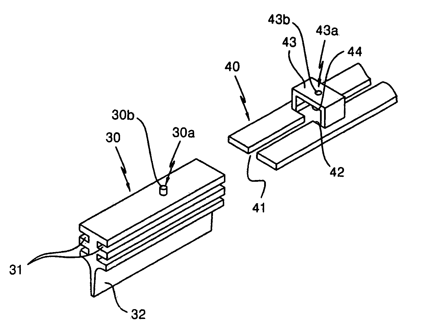
[0048] A press-formed tensile member 40 having a predetermined tensility is constituted in a single piece that extends symmetrically outward from a central portion thereof, and functions as both a lone tension spring and skeletal frame that attaches to a wiper arm.

[0049] A slot 41 is cut in a longitudinal direction along the central portion of the tensile member 40 in order to insert the portion of the blade 30 between the insertion grooves 31 formed on either side of the blade 30. A mounting groove 42 is centrally formed at a central portion in an appropriate location on the slot 41. A guiding member is provided at the top of the mounting receptacle 42 for guiding the top portion of the blade 30 when it is inserted and aligned along the slot 41 to support and fix the blade 30.

[0050] Also, an assembly...


PUM


Abstract

Provided is an automotive wiper that has a frame, which supports a rubber blade, is formed in one piece with a tension spring, and is easily assembled with the blade. A tensile member (40) symmetrically extends in one piece from a center of the wiper in opposite directions to form both a single-piece tension spring and skeletal frame. A slot (41) is centrally cut along a length of the tensile member to insert the blade (30) therein. A blade mounting receptacle (42) is formed at a center of the slot to insert the blade for its assembly. A guiding member (43) is formed above the mounting receptacle. An assembly guide (43a) is formed on the guiding member to center the blade for assembly. A coupling positioner (30a) is centrally disposed on a surface of the blade to position the blade for assembly with respect to the assembly guide formed on the guiding member.

Description

BACKGROUND OF THE INVENTION [0001] 1. Field of the Invention [0002] The present invention relates to an automotive wiper, and more particularly, to an automotive wiper that forms a frame holding a rubber blade of the wiper and a tension spring for maintaining tension on the rubber blade in one piece and which has a structure that allows easy installation and removal of the rubber blade on and from the wiper frame. [0003] 2. Description of the Related Art [0004] An automotive wiper is operated by a wiper motor through a mechanical linkage that moves the wiper arm back and forth in a predetermined arc. Disposed on the end of the wiper arm is a detachably mounted wiper frame to which a wiper blade made of rubber is attached. [0005] Conventional wipers attached to wiper arms include a skeletal frame and a blade portion mounted on the frame and contacting a windshield to wipe it in a pendular movement, as shown in FIGS. 1 through 3. [0006] A conventional wiper includes: a main frame 12 h...

Claims


Application Information

Patent Timeline
Patent Type & Authority Applications(United States)
IPC IPC(8): B60S1/38
CPCB60S1/38B60S1/3806B60S2001/3841B60S1/381B60S2001/382B60S1/3808
Inventor PARK, SE-HEON
Owner PARK LTD
Why Eureka
Try Eureka