Oil separating structure of automatic transmission

Active Publication Date: 2006-03-30
JATCO LTD
View PDF26 Cites 30 Cited by
  • Summary
  • Abstract
  • Description
  • Claims
  • Application Information

AI Technical Summary

Benefits of technology

[0008] It is therefore an object of the present invention to provide an oil separating structure of an automati

Problems solved by technology

Therefore, the oil strainer is unlike

Method used


Image

  • Oil separating structure of automatic transmission
  • Oil separating structure of automatic transmission
  • Oil separating structure of automatic transmission

Examples


Embodiment Construction

[0025] The present invention will now be described in detail in accordance with the accompanying drawings showing a preferred embodiment thereof.

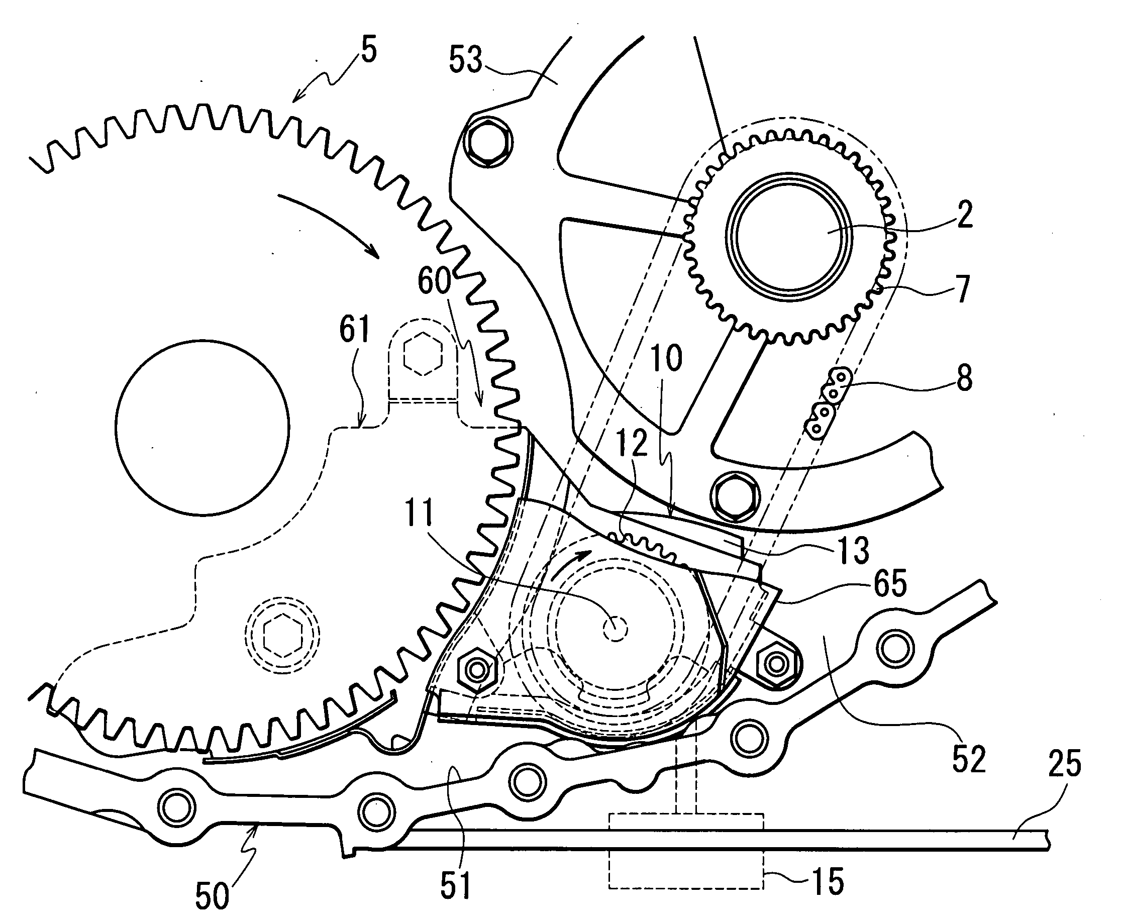
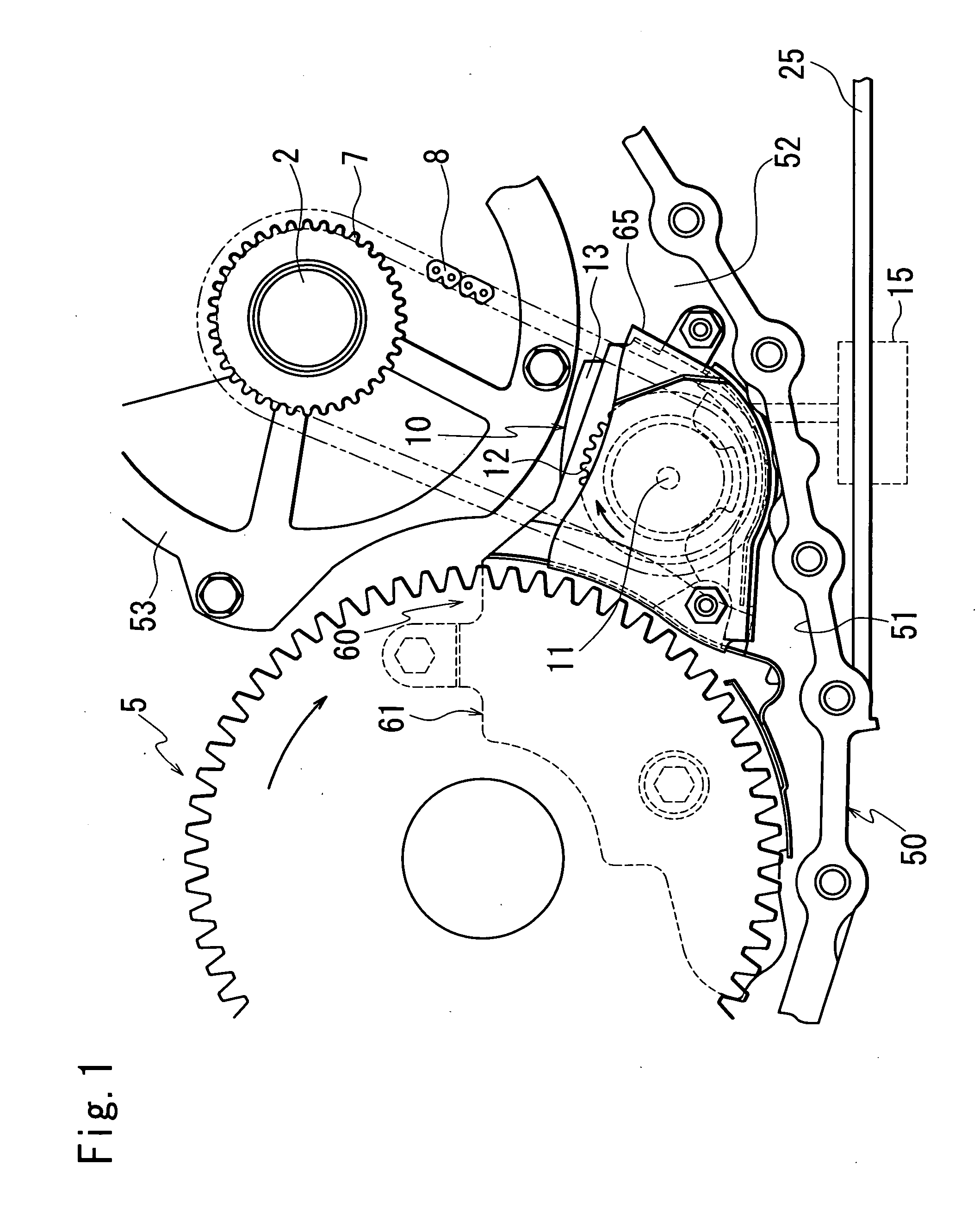
[0026]FIG. 1 is a front view showing an oil separating structure of an automatic transmission according to an embodiment of the present invention.

[0027] Power from an engine, not shown, is transmitted to an input shaft (hereinafter referred to as a primary shaft) 2 of an automatic transmission through a torque converter, not shown.

[0028] The power input to the primary shaft 2 is transmitted to a reduction gear, not shown, after engine revolutions are converted by a shift mechanism, not shown, comprised of a primary pulley provided on the primary shaft 2, a secondary pulley provided on a secondary shaft, and a V belt wound over the primary pulley and the secondary pulley. The reduction gear is engaged with a final gear 5 of a differential, so that power is transmitted from the reduction gear to the differential.

[0029] The power transmitt...


PUM


Abstract

There is provided an oil separating structure of an automatic transmission, which makes it difficult for an oil strainer of an oil pump to draw oil containing air bubbles. A baffle plate base separates a space around the oil strainer and a space around a driven sprocket as well as a final gear, and therefore, oil containing air bubbles formed as a result of agitation by the driven sprocket, chain, and final gear does not flow directly into the oil strainer. As a result, the oil strainer is unlikely to draw oil containing air bubbles.

Description

BACKGROUND OF THE INVENTION [0001] 1. Field of the Invention [0002] The present invention relates to an oil separating structure for separating oil around rotating bodies in an automatic transmission. [0003] 2. Description of the Related Art [0004] There has been an automatic transmission in which an oil pump is disposed apart from an input shaft, so that rotational driving force from the input shaft is transmitted to a driven sprocket of the oil pump via a chain to drive the oil pump. [0005] An example of this automatic transmission has been disclosed in Japanese Laid-Open Patent Publication (Kokai) No. 2003-156127. [0006] In this automatic transmission, an oil pump is installed in an upper part of a shift mechanism that converts engine revolutions, and driving force from an input shaft is transmitted to the oil pump via a chain. [0007] In this automatic transmission, however, if the oil pump is disposed within oil in the lower part of a transmission case, the oil is agitated by ro...

Claims


Application Information

Patent Timeline
IPC IPC(8): F16H57/04F16N31/00B60K20/00F16H57/02F16H57/023
CPCF16H57/0404F16H57/0406F16H57/0408Y10T74/20183F16H57/05F16H2061/004Y10T74/2186F16H57/0423
Inventor TOMINAGA, MASAKAZUSAITOU, TSUTOMUTAGUCHI, HIROMIKUNII, YASUHIKO
Owner JATCO LTD
Why Eureka
Try Eureka