Inverted microscope

a microscope and inverted technology, applied in the field of inverted microscopes, can solve the problems of blurred viewing field, inconvenience, and inability to give optimal optical performan

Inactive Publication Date: 2006-03-30
OLYMPUS CORP
View PDF5 Cites 20 Cited by
  • Summary
  • Abstract
  • Description
  • Claims
  • Application Information

AI Technical Summary

Benefits of technology

[0011] In view of the foregoing, an object of the present invention is to provide an inverted microscope in which plural split optical paths can be selected without degradation of hardness and optical characteristics of the inverted microscope.
[0013] According to the inverted microscope of the present invention, plural combined / split optical paths can be suitably selected as necessary for use without degradation in hardness and optical characteristics. Thus, an inverted microscope with high versatility can be provided.

Problems solved by technology

In addition, since the point of focus significantly changes in a direction of an optical axis by the addition of the optical system, an optimal optical performance cannot be given and a viewing field is blurred.
Such inconveniences are incurred from difficulties in designing an optimal optical system for two optical paths with different lengths, i.e., optical path lengths from the objective lens to the observer before and after the addition of the optical system.

Method used


Image

  • Inverted microscope
  • Inverted microscope
  • Inverted microscope

Examples


first embodiment

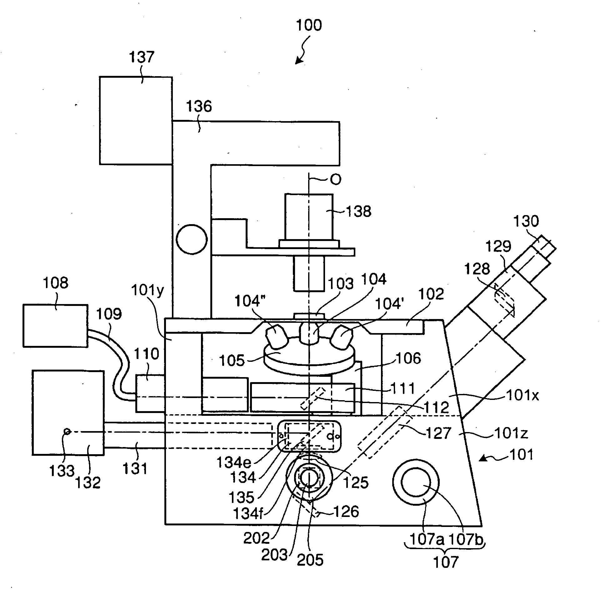
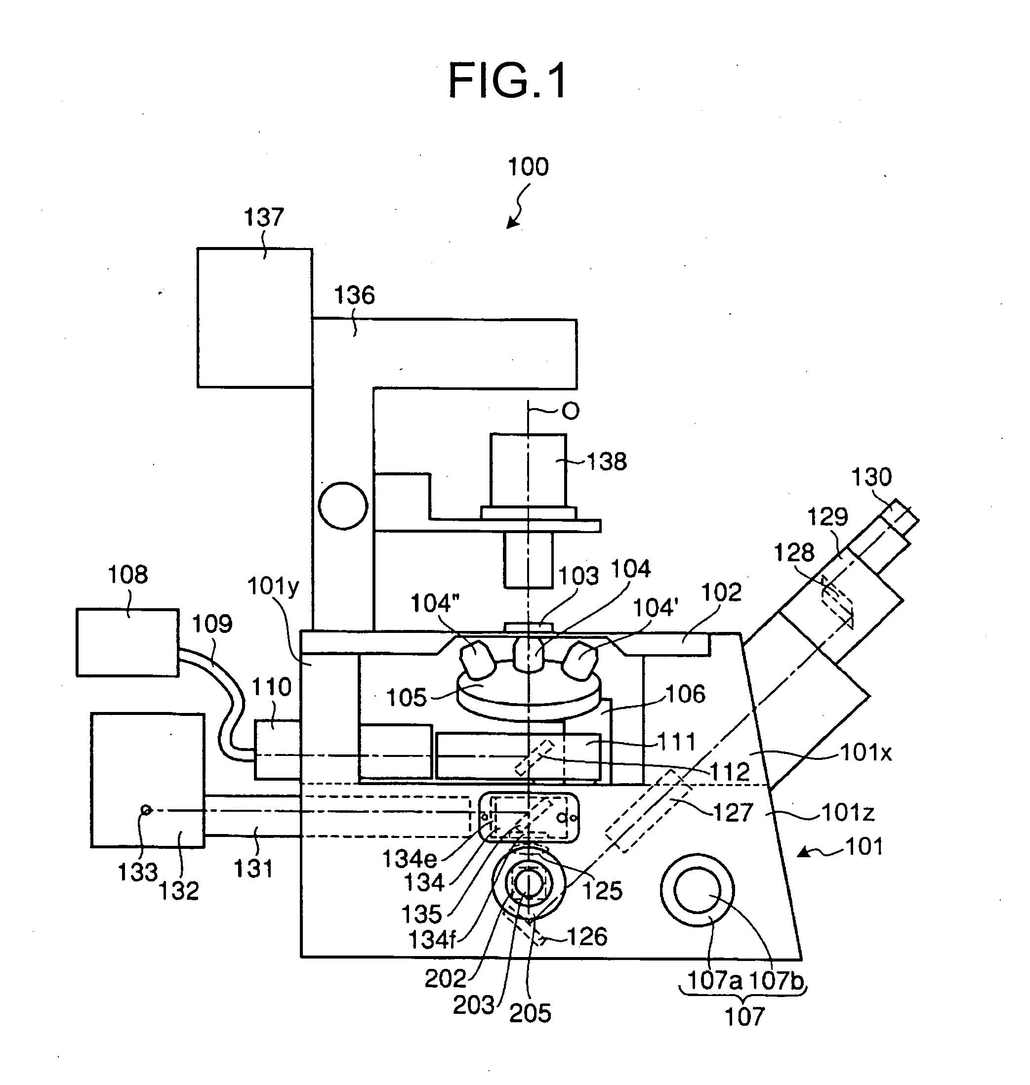
[0045] As can be seen from above, in the inverted microscope 100 of the first embodiment, the dichroic mirror 135 and the dichroic mirror 112 respectively function as an optical path combining / splitting element which combines an optical path with a main optical path and splits the main optical path extending along the optical axis O between the objective lens 104 and the imaging lens 125. The imaging lens 125 is an optical element that serves to form an optical image of the sample 103 in cooperation with the objective lens 104. With the objective lens 104 transmitting the light from various points on the sample 103 as parallel light beams, the main optical path between the objective lens 104 and the imaging lens 125 is formed as a path for parallel light. The dichroic mirror 135 and the dichroic mirror 112 are positioned on and off the optical axis O between the objective lens 104 and the imaging lens 125, respectively. The projection tube 131 and the projection tube 110 serve as an...

second embodiment

[0061] as described above, no matter whether one combined / split optical path is employed or plural combined / split optical paths are employed, the height of the stage and the distance between the imaging lens and the objective lens do not change at all, whereby the degradation of the hardness and the optical characteristics of the microscope itself can be prevented. Further, with the disposition of a manipulation unit at a side of the observer, a throughput of the experiments can be improved.

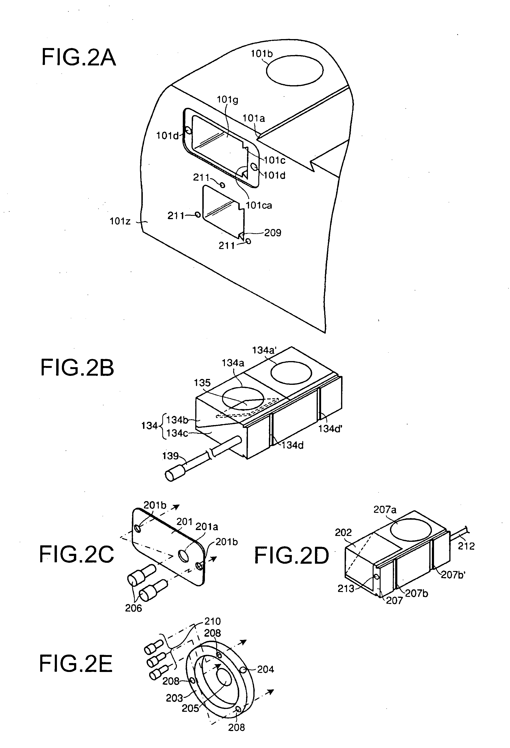
[0062] The present invention is not limited to the embodiments as described above. As far as the optical path combining / splitting element that forms the combined / split optical path without reconstruction of the microscope can be attached to and detached from the base 101z from a side surface thereof, the optical path combining / splitting element may be structured as to be attached to and detached from a side of the observer as to improve the handling of the optical path combining / splitting elemen...


PUM


Abstract

An inverted microscope includes a stage on which a sample is disposed, a support which supports the stage, a base which holds the support from below the support, an objective lens which is arranged under the sample and the stage, an imaging lens which is arranged inside the base and which forms an optical image of the sample in cooperation with the objective lens, and an optical path combining / splitting unit which is arranged on a main optical path between the objective lens and the imaging lens and which detachably holds the optical path combining / splitting element that combines / splits the main optical path inside the base.

Description

CROSS-REFERENCE TO RELATED APPLICATIONS [0001] This application is based upon and claims the benefit of priority from the priority Japanese Patent Application No. 2004-280014, filed on Sep. 27, 2004; the entire contents of which are incorporated herein by reference. BACKGROUND OF THE INVENTION [0002] 1. Field of the Invention [0003] The present invention relates to an inverted microscope which allows observation of a sample disposed on a stage from below via an objective lens. [0004] 2. Description of the Related Art [0005] Japanese Patent Application Laid-Open No. H11-223773 discloses an inverted microscope having a plurality of incident lighting optical paths as shown in FIG. 8. An experiment through Caged reagent release is carried out as follows. First, a laser beam emitted from a laser light source 1 for photorelease of Caged reagent is guided through an optical path of a first incident lighting system to a sample 5 via a dichroic mirror DM1 in a cube CV1. Then, through manipul...

Claims


Application Information

Patent Timeline
Patent Type & Authority Applications(United States)
IPC IPC(8): G02B21/00
CPCG02B21/0088
Inventor KOUNO, TAKAYUKIAONO, YASUSHI
Owner OLYMPUS CORP
Why Eureka
Try Eureka