On-substrate microlens to couple an off-substrate light emitter and/or receiver with an on-substrate optical device

a technology of optical devices and microlens, which is applied in the direction of optical waveguide light guides, instruments, optics, etc., can solve the problems of time-consuming and expensive active alignment process, and difficulty in aligning optical fibers, waveguides, or other light emitters and/or receivers with optical devices on dies or other substrates

Inactive Publication Date: 2006-03-30
INTEL CORP
View PDF26 Cites 30 Cited by
  • Summary
  • Abstract
  • Description
  • Claims
  • Application Information

AI Technical Summary

Problems solved by technology

The alignment of an optical fiber, waveguide, or other light emitter and/or receiver with an optical device on a die o

Method used


Image

  • On-substrate microlens to couple an off-substrate light emitter and/or receiver with an on-substrate optical device
  • On-substrate microlens to couple an off-substrate light emitter and/or receiver with an on-substrate optical device
  • On-substrate microlens to couple an off-substrate light emitter and/or receiver with an on-substrate optical device

Examples


Embodiment Construction

[0020] In the following description, numerous specific details are set forth. However, it is understood that embodiments of the invention may be practiced without these specific details. In other instances, well-known circuits, structures and techniques have not been shown in detail in order not to obscure the understanding of this description.

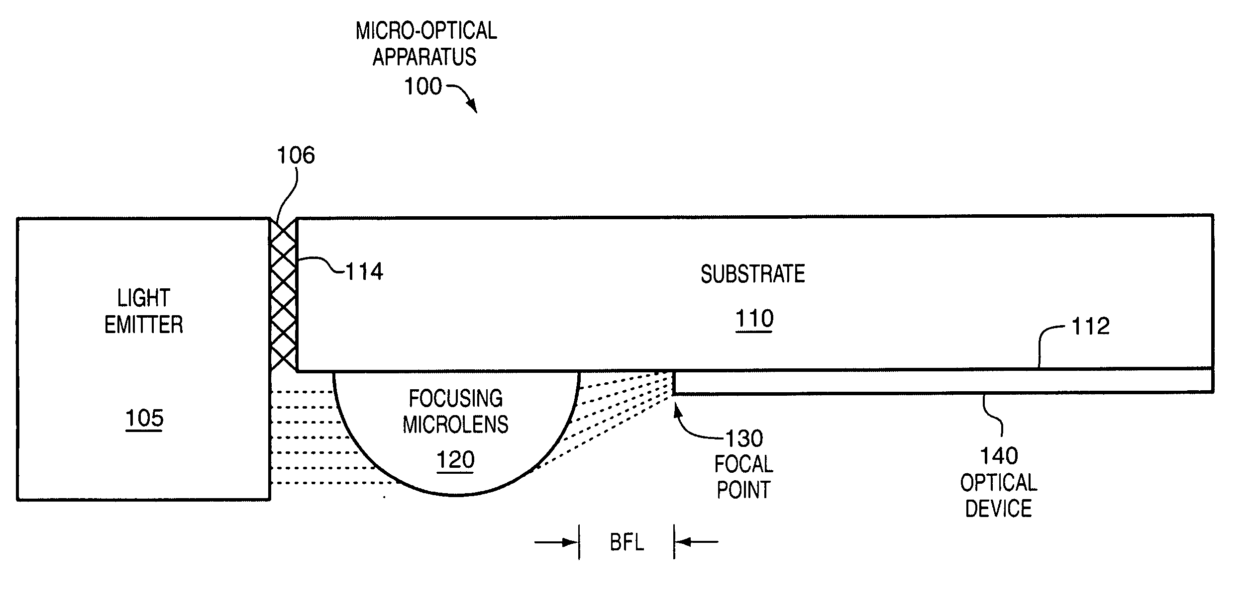
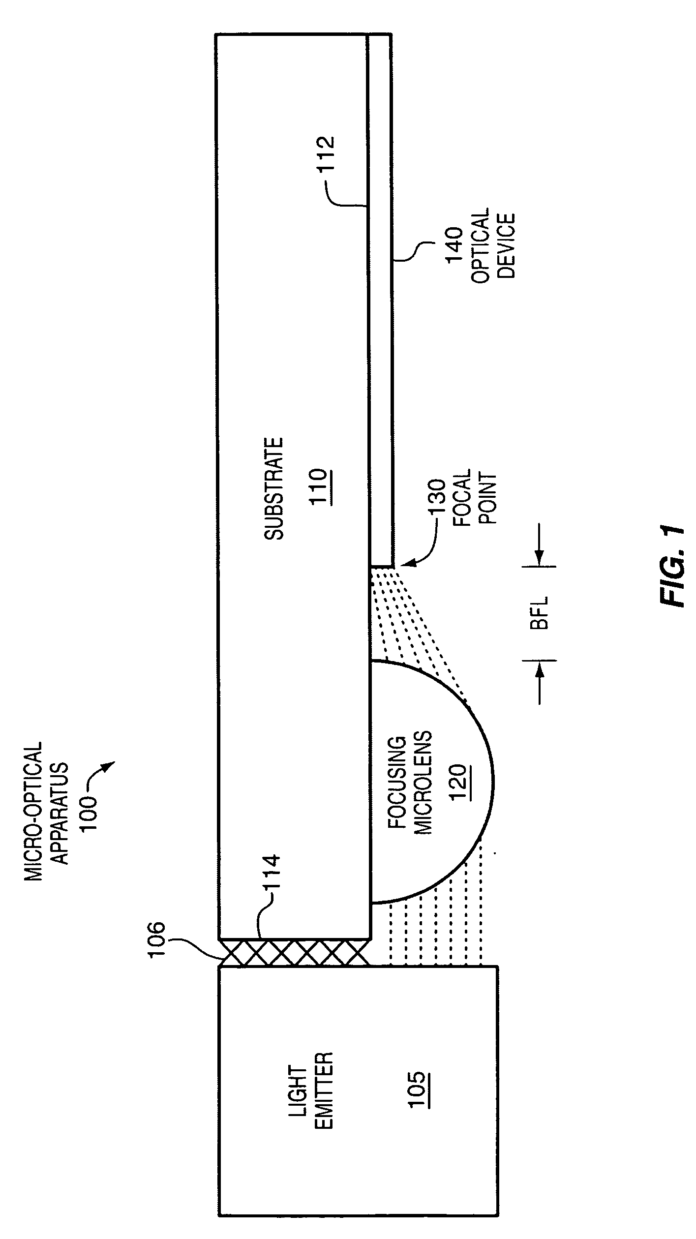
[0021]FIG. 1 shows an enlarged cross-sectional view of an optical apparatus 100 that is coupled with an off-substrate light emitter 105, according to one or more embodiments of the invention. The optical apparatus includes a substrate 110, such as, for example, a die, other microelectronic device, or printed circuit, an on-substrate focusing microlens 120 that is coupled with the substrate to receive light from the off-substrate light emitter, and focus the light toward, but not necessarily to, a focal point 130, and an on-substrate optical device 140, such as, for example, in the illustrated embodiment a waveguide, that is coupled with the s...


PUM


Abstract

Optical apparatus, methods of forming the apparatus, and methods of using the apparatus are disclosed herein. In one aspect, an optical apparatus may include a substrate, an on-substrate microlens coupled with the substrate to receive light from an off-substrate light emitter and focus the light toward a focal point, and an on-substrate optical device coupled with the substrate proximate the focal point to receive the focused light. Communication of light in the reverse direction is also disclosed. Systems including the optical apparatus are also disclosed.

Description

BACKGROUND [0001] 1. Field [0002] An embodiment of the invention relates to an apparatus including a microlens. [0003] 2. Background Information [0004] The alignment of an optical fiber, waveguide, or other light emitter and / or receiver with an optical device on a die or other substrate may be challenging. An active alignment process may be used to improve the alignment. However, the active alignment process may tend to be time consuming and expensive. BRIEF DESCRIPTION OF THE SEVERAL VIEWS OF THE DRAWINGS [0005] The invention may best be understood by referring to the following description and accompanying drawings that are used to illustrate embodiments of the invention. In the drawings: [0006]FIG. 1 shows an enlarged cross-sectional view of an optical apparatus that is coupled with an off-substrate light emitter, according to one or more embodiments of the invention. [0007]FIG. 2 shows a spherical ball lens focusing a beam of light to a focal point, according to one aspect. [0008...

Claims


Application Information

Patent Timeline
IPC IPC(8): G02B6/12
CPCG02B6/4206G02B6/42
Inventor TOWLE, STEVENBRAUNISCH, HENNINGLU, DAOQIANGVANDENTOP, GILROY J.GEORGE, ANNA
Owner INTEL CORP
Why Eureka
Try Eureka