Vertical displacement device

Inactive Publication Date: 2005-09-06
UNIV OF FLORIDA RES FOUNDATION INC
View PDF4 Cites 102 Cited by
  • Summary
  • Abstract
  • Description
  • Claims
  • Application Information

AI Technical Summary

Problems solved by technology

The vertical displacement device may also operate in modes where the tilt of the vertical displacement device and the tilt of the frame are not equal, which results in the vertically displaceable platform being tilted relative to the Z-axis and not positioned in a plane orthogonal to the Z-axis.

Method used


Image

  • Vertical displacement device
  • Vertical displacement device
  • Vertical displacement device

Examples


Embodiment Construction

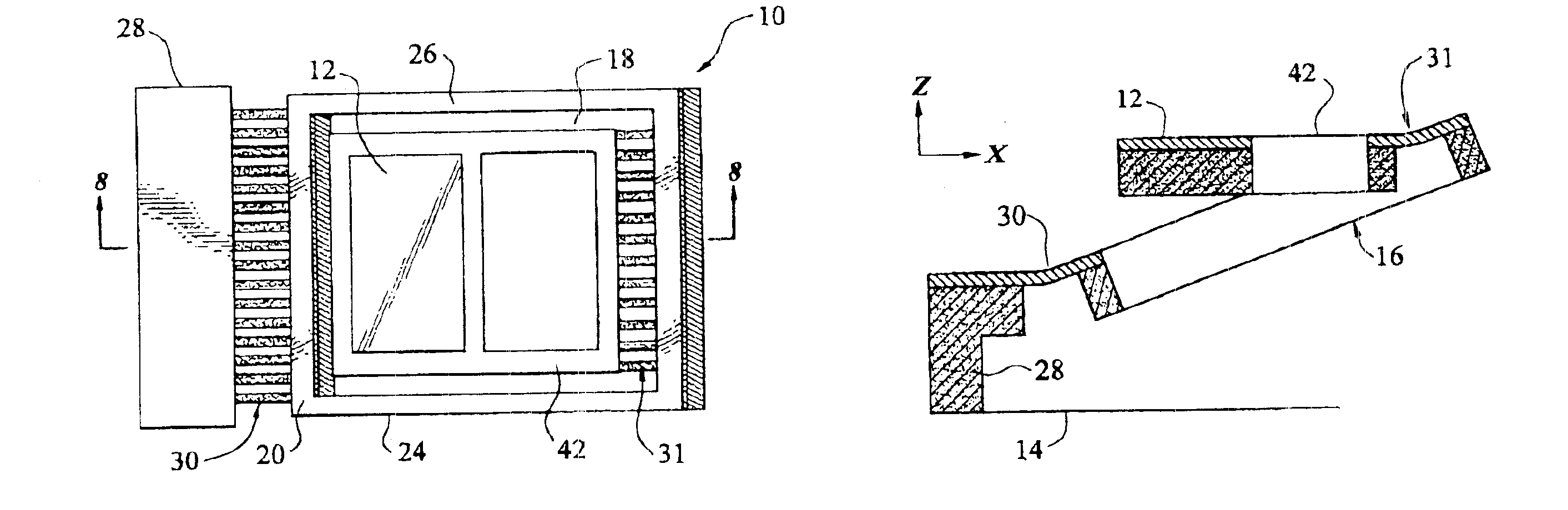
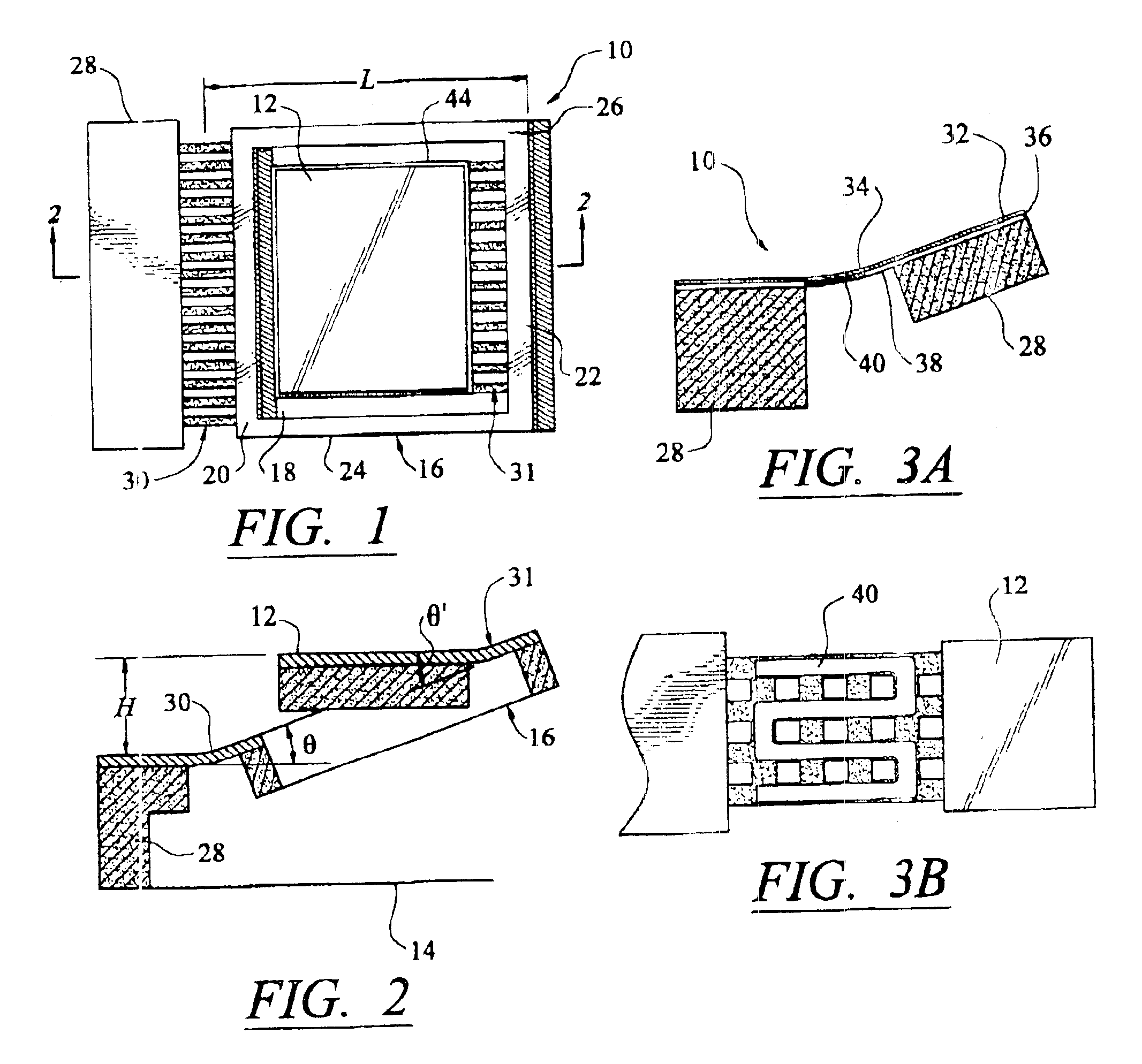
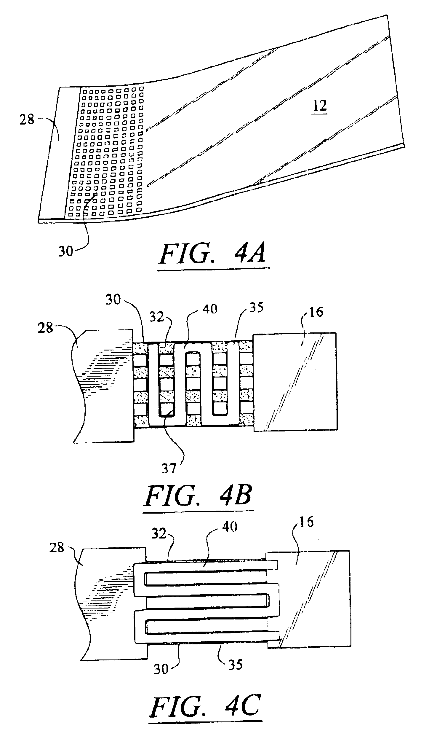
[0035]As shown in FIGS. 1-18, this invention is directed to a vertical displacement device 10, which may be referred to as a large vertical displacement device (LVD), capable of raising one or more vertically displaceable platforms 12 along a Z-axis relative to a base 14. In particular, vertical displacement device 10 may be capable of raising vertically displaceable platform 12 along a Z-axis so that vertically displaceable platform 12 remains generally parallel to base 14. Generally, the vertical displacement device 10 lies in a single plane while in an unactuated position. The vertical displacement device 10 may be moved along the Z-axis by actuating at least two thermal actuators using an electrical current. In at least one embodiment, vertical displacement device 10 is a microelectromechanical (MEMS) device that is capable of functioning on a small scale. Vertically displaceable platform 12 may be, but is not limited to, a microlens, a micromirror, a micro-grating, or other dev...


PUM


Abstract

A MEMS vertical displacement device capable of moving one or more vertically displaceable platforms relative to a base. In particular, the vertical displacement device may be capable of moving a vertically displaceable platform so that the vertically displaceable platform remains generally parallel to a base. The vertically displaceable platform may be, but is not limited to, a microlens, a micromirror, micro-grating, or other device. The vertical displacement device may also be included in optical coherence and confocal imaging systems.

Description

CROSS-REFERENCE TO RELATED APPLICATION[0001]This application claims the benefit of U.S. Provisional Application No. 60 / 467,225, filed May 1, 2003.FIELD OF THE INVENTION[0002]This invention is directed generally to vertical displacement devices, and more particularly to microelectromechanical vertical displacement devices and use of these devices in biomedical applications.BACKGROUND[0003]Microelectromechnical system (MEMS) devices are devices that operate on a very small scale, typically in a range of tens of microns to a few millimeters. MEMS devices mostly are fabricated using integrated circuits (IC) technology. Production of MEMs devices, likewise, enables one to realize relatively low manufacturing costs because of the batch fabrication techniques and the small size of the devices. In some applications MEMS devices are imperceptible to the unaided human eye. MEMS devices include many different devices used for a variety of purposes. One device in particular is a movable micromi...

Claims


Application Information

Patent Timeline
Patent Type & Authority Patents(United States)
IPC IPC(8): B81B3/00G02B6/35G02B26/08
CPCB81B3/0018G02B26/0866B81B2201/038B81B2201/06G02B6/3512G02B6/3526G02B6/3534G02B6/3584
Inventor XIE, HUIKAI
Owner UNIV OF FLORIDA RES FOUNDATION INC
Why Eureka
Try Eureka