
Lens module assembly method and assembly intermediate

Inactive Publication Date: 2006-03-30
EASTMAN KODAK CO
View PDF2 Cites 8 Cited by
  • Summary
  • Abstract
  • Description
  • Claims
  • Application Information

AI Technical Summary

Benefits of technology

[0005] It is an advantageous effect of the invention that an improved lens module assembly methods and assembly intermediates, in which incorrect lens placement can be simply and easily prevented.
that an improved lens module assembly methods and assembly intermediates, in which incorrect lens placement can be simply and easily prevented.

Problems solved by technology

In both cases, mistakes can be made as to the orientation of individual optical elements.
Such mistakes can occur during placement in the lens module or during an earlier step.
These methods tend to be cumbersome and add cost.

Method used


Image

  • Lens module assembly method and assembly intermediate
  • Lens module assembly method and assembly intermediate
  • Lens module assembly method and assembly intermediate

Examples


Embodiment Construction

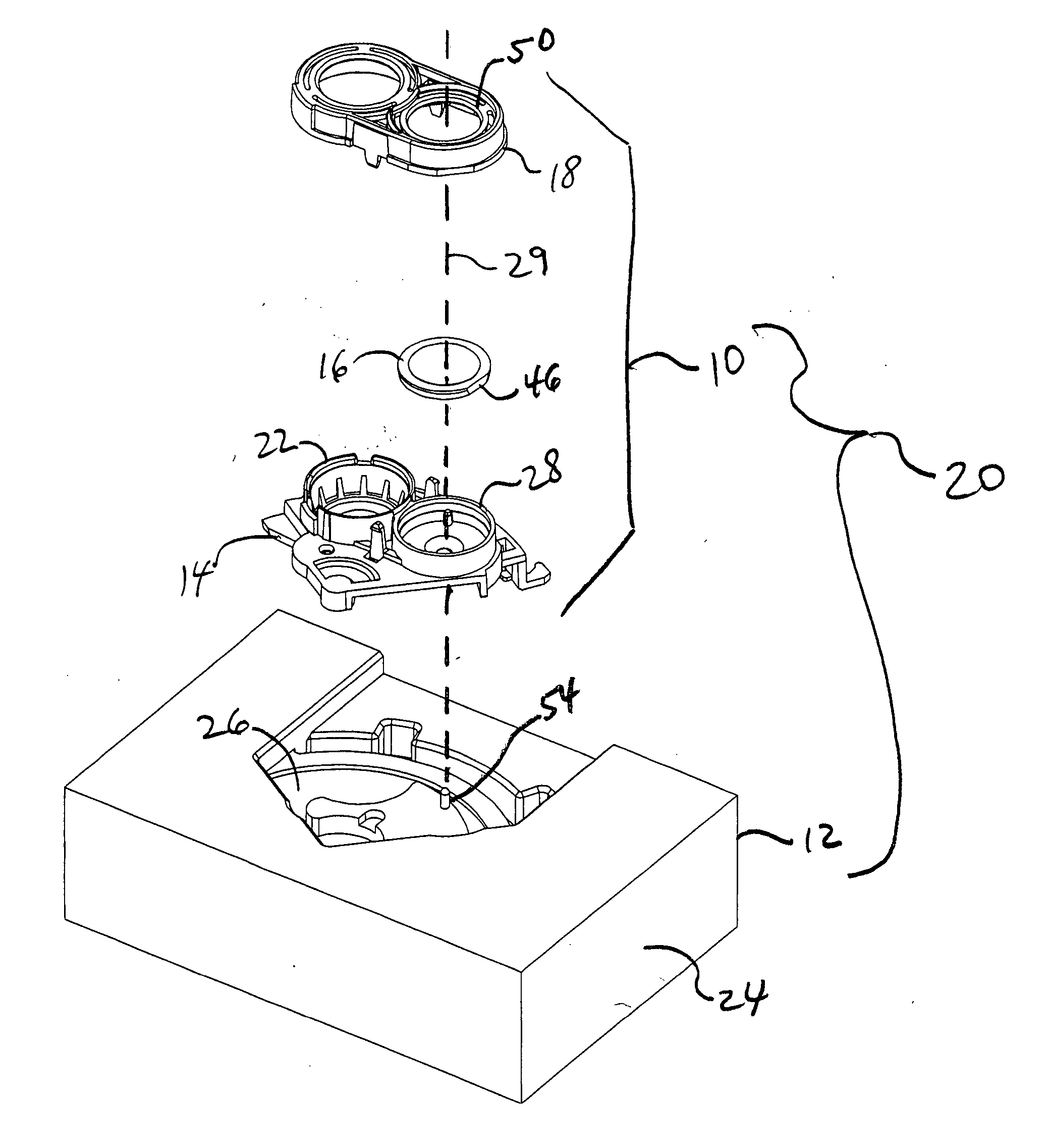
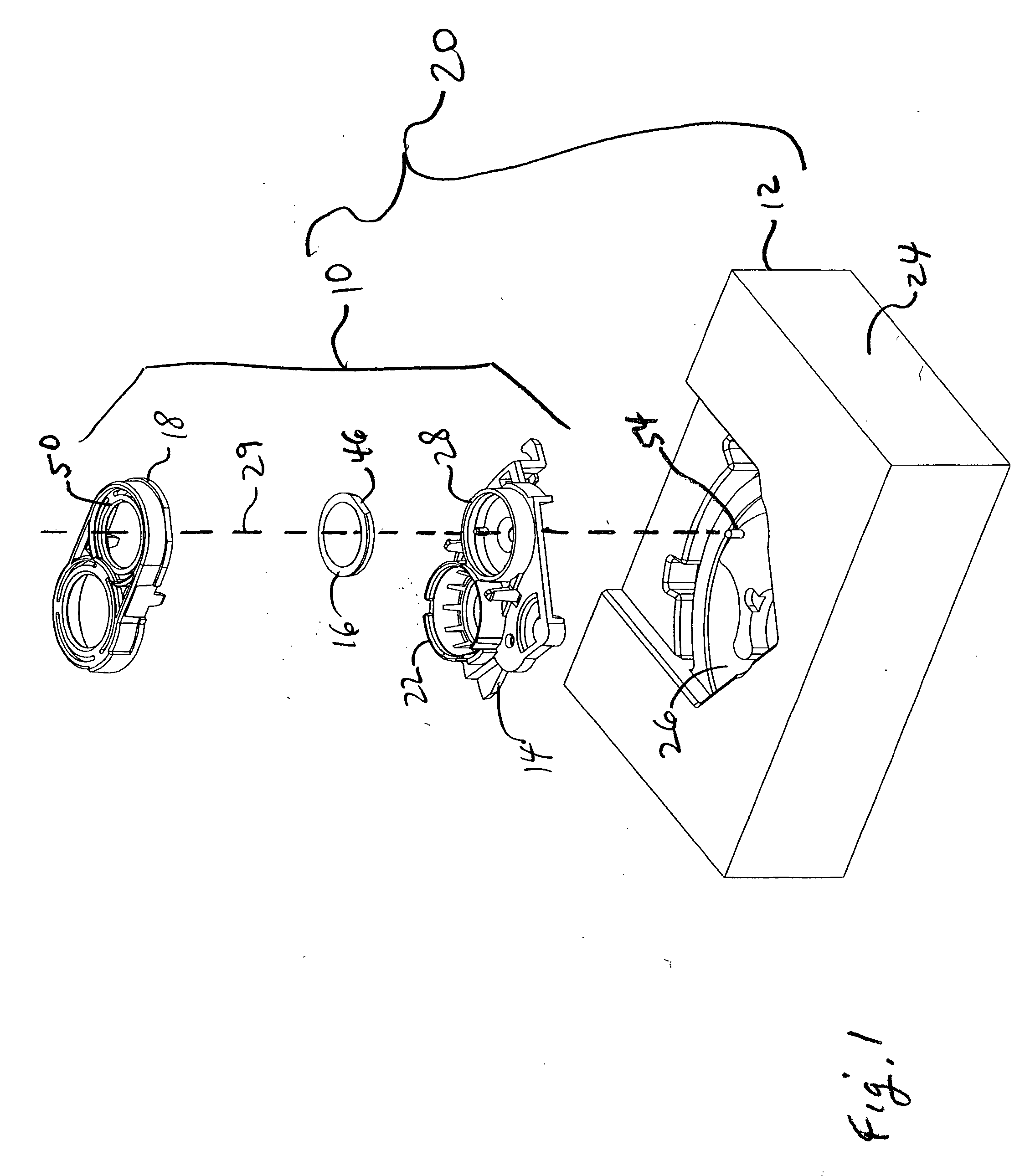
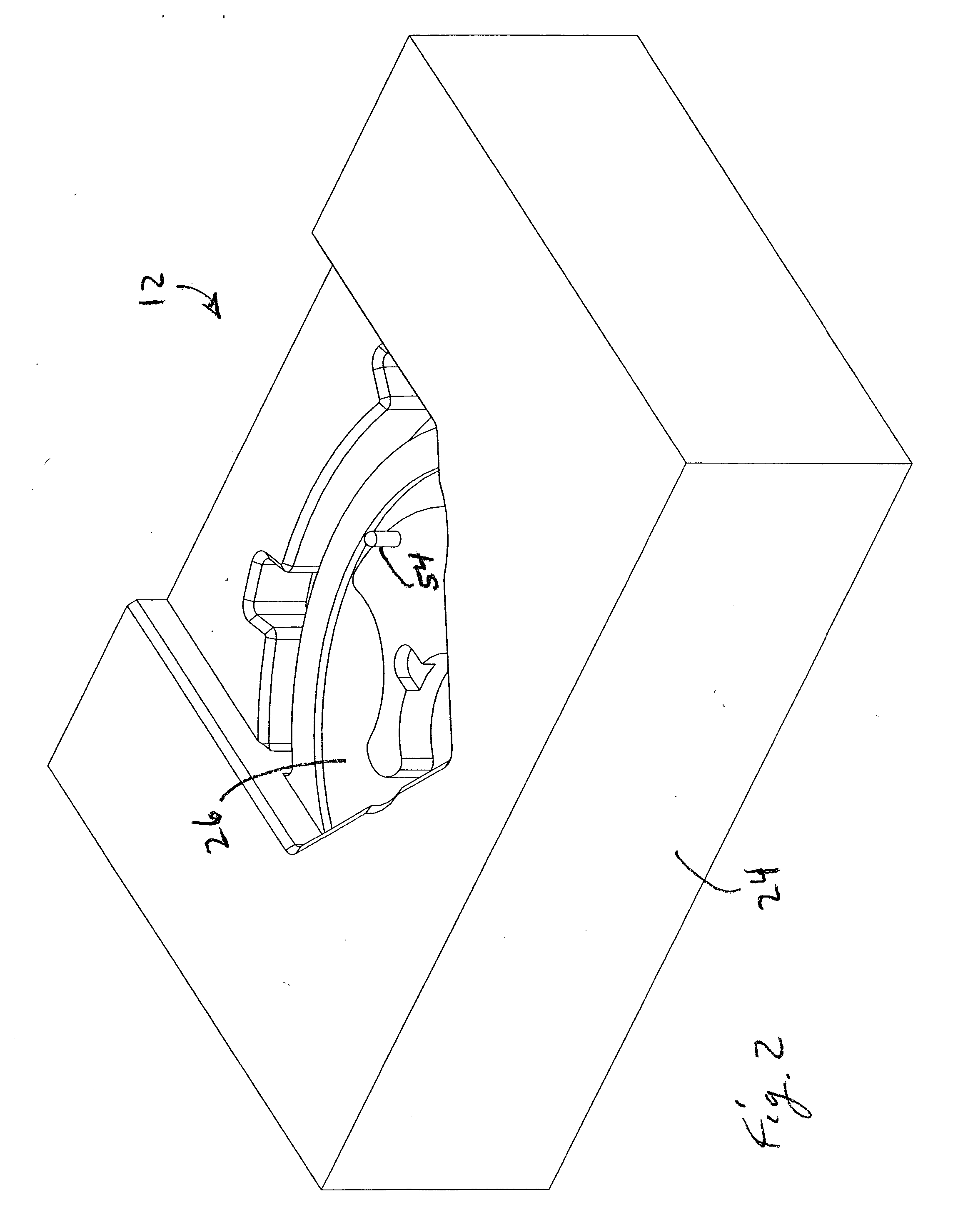
[0011] In the methods herein, a lens module 10 is assembled using a fixture 12. The lens module 10 has a lens holder 14, which is received by the fixture 12, a lens element 16, and a lens retainer 18. When the lens module 10 is completed, the lens retainer 18 is connected to the lens holder 14 and holds the lens element 16 in place.

[0012] The term “assembly intermediate” is used herein to refer to an assembly of a fixture 12 and the lens holder 14, with or without the assembled lens element 16 and a lens retainer 18. The assembly intermediate 20 illustrated in the figures is produced during assembly of a lens module 10 of a one-time use camera. The assembly intermediate 20 can produced and retained in one location or can be transported manually or on a moving conveyor or the like (not shown). The assembly intermediate 20 is convenient for transport, particularly after the lens module 10 is completed, since the lens module 10 is held in a known orientation and position on the fixtur...


PUM


Abstract

In a lens module assembly method, a lens holder is placed in a receiver. The lens holder has a nest. A lens element is deposited in the lens holder. During the depositing, the lens element seats in the nest, if the lens element is in a forward-facing orientation. Entry of the lens element into the nest is interrupted, if the lens element is in a rearward-facing orientation.

Description

FIELD OF THE INVENTION [0001] The invention relates to photographic cameras and lens modules and more particularly relates to assembly of lens modules. BACKGROUND OF THE INVENTION [0002] Lens modules for one time use cameras and other optical devices are commonly made by assembling lens components, such as optical elements and aperture stops into a holder and attaching a retainer to hold the lens components in place. The assembly can be manual or automated. In both cases, mistakes can be made as to the orientation of individual optical elements. Such mistakes can occur during placement in the lens module or during an earlier step. For example, an individual lens element can have been positioned upside down in a rack or the like, which feeds an automated assembly tool. Once the lens module is assembled, it is not immediately apparent that one or more optical elements may have been reversed. Optical testing and other methods can be used to determine if the placement is correct. These ...

Claims


Application Information

Patent Timeline
IPC IPC(8): G03B17/02
CPCG03B17/02G03B2217/002G03B17/12
Inventor WIRT, MICHAEL L.
Owner EASTMAN KODAK CO
Learn More