Printing system

a printing system and fuser technology, applied in the field of fusers for printing systems, can solve the problems of non-uniformities on the surface, non-uniformities in gloss, etc., and achieve the effects of high gloss, low reliability of color fusers, and high gloss

Inactive Publication Date: 2006-03-30
XEROX CORP
View PDF98 Cites 112 Cited by
  • Summary
  • Abstract
  • Description
  • Claims
  • Application Information

AI Technical Summary

Benefits of technology

[0026] The reliability of color fusers tends to be low when compared with the other components of a printing machine and with black and white fusers. This is primarily because higher temperatures and longer nip dwell times are typically employed to achieve higher gloss levels for color images. To achieve a high gloss at reasonable temperatures, the surface smoothness (Ra) is generally about 0.4 microns or les

Problems solved by technology

The reliability of color fusers tends to be low when compared with the other components of a printing machine and with black and white fusers.
Over time, the color fuser roll tends to wear, resulting in non-uniformities in the surface of the roll, which, in turn, lead to gloss non-uniformities.
Additionally, the lifetime of the fuser roll material is limited by the desire to provide compressibility to achieve an adequate nip width, which affects the dwell time for heating, and provide sufficient differential speeds to enable stripping and release.
However

Method used


Image

  • Printing system
  • Printing system
  • Printing system

Examples


Embodiment Construction

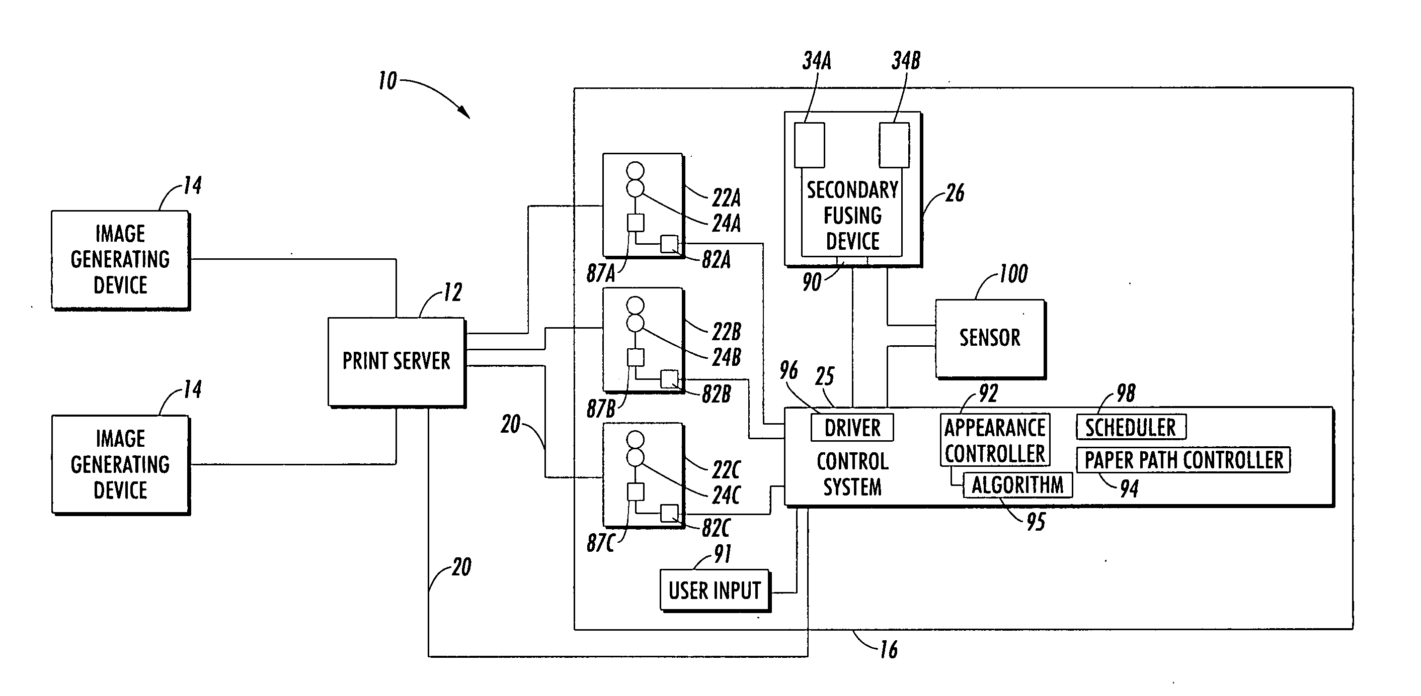
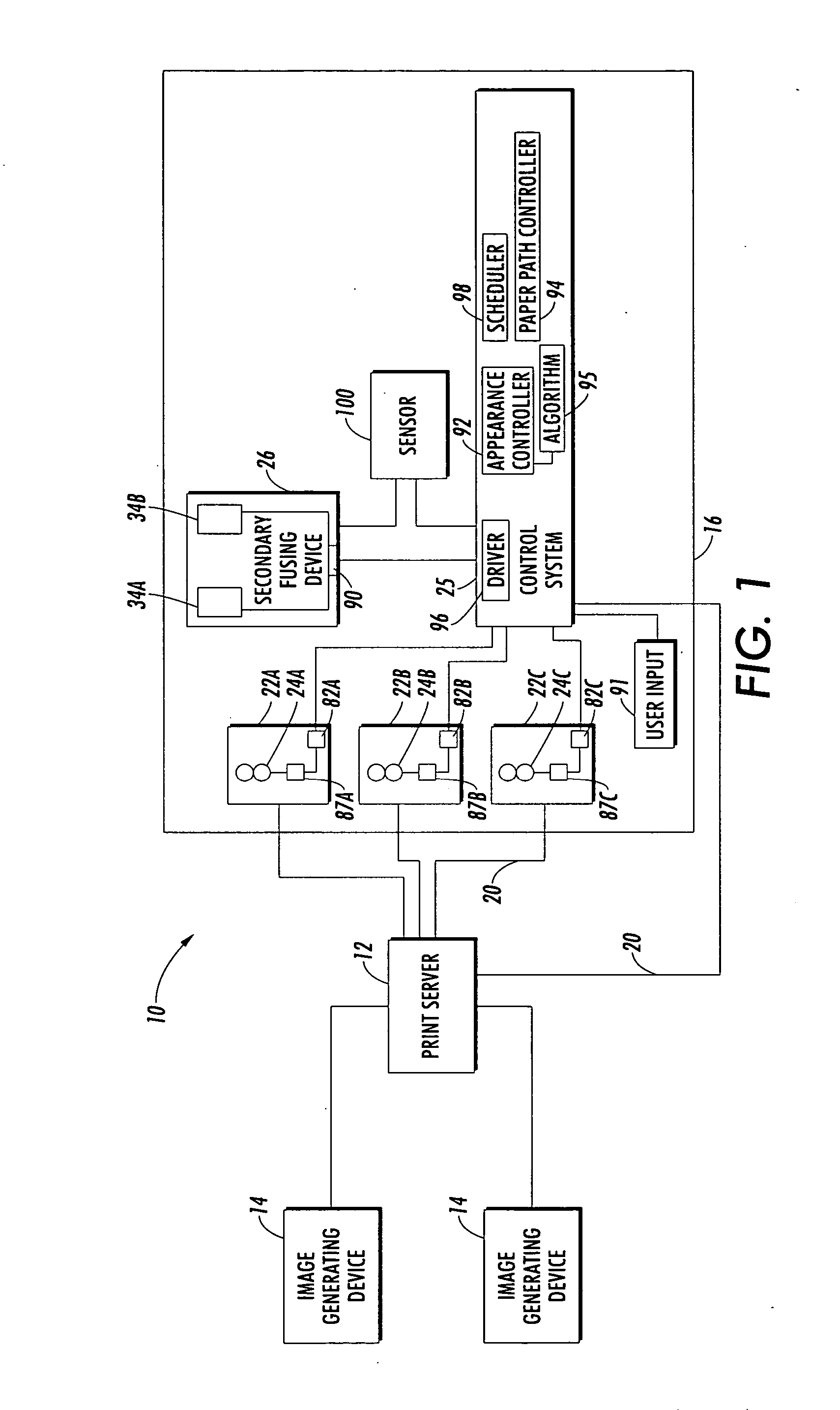
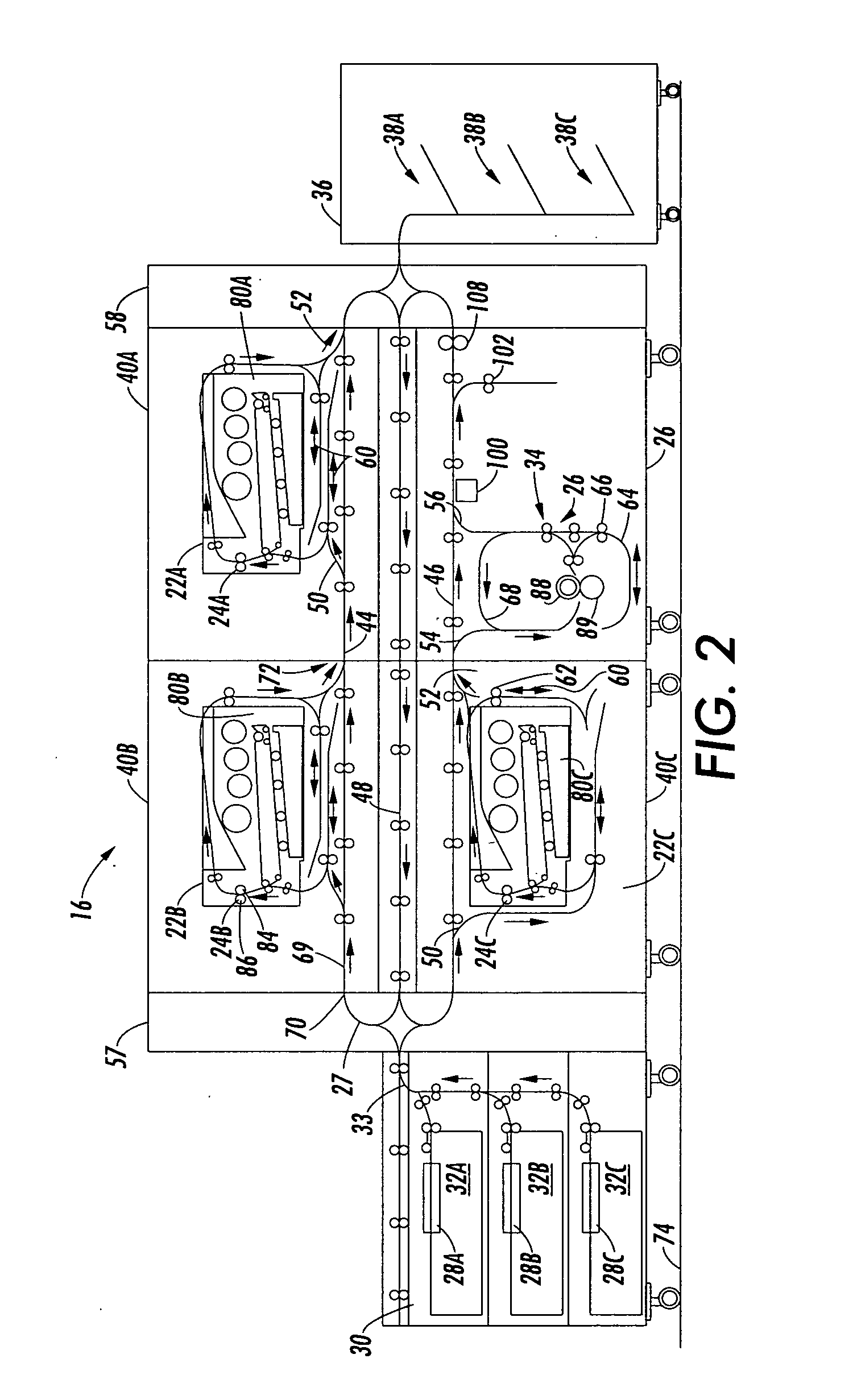
[0040] A printing system is disclosed which includes one or a plurality of marking devices which supply printed media, such as sheets, to a common secondary fusing device. A marking device, as used herein, may encompass any device for applying an image to print media. Print medium may encompass a usually flimsy physical sheet of paper, plastic, or other suitable physical print media substrate for images, whether precut or web fed. In one embodiment, the common secondary fusing device augments the fusing performance of primary fusing devices resident in the marking devices. In another embodiment, a secondary fusing module includes at least two secondary fusing devices, each of which is capable of receiving printed media from two or more marking devices. The marking device(s) and secondary fusing device(s) may be under the control of a common control system for printing images from a common electronic print job stream. The printing system generates a print job or document, which is no...


PUM


Abstract

A printing system includes first and second marking devices for applying images to print media. A first primary fusing device is associated with the first marking device for applying a primary fusing treatment to the images applied to print media by the first marking device. A second primary fusing device is associated with the second marking device for applying a primary fusing treatment to the images applied to print media by the second marking device. At least one secondary fusing device receives printed media from the first and second marking devices. The secondary fusing device selectively applies a further fusing treatment to at least a portion of the images applied to the printed media to increase a uniformity of an appearance characteristic between printed images generated by the first marking device and the second marking device.

Description

[0001] This application claims the benefit of the following copending U.S. applications, the disclosures of which are incorporated herein in their entireties, by reference: U.S. Provisional Application Ser. No. 60 / 631,918, filed Nov. 30, 2004 (Attorney Docket No. 20031867-US-PSP), entitled “PRINTING SYSTEM WITH MULTIPLE OPERATIONS FOR FINAL APPEARANCE AND PERMANENCE,” by David G. Anderson et al., and U.S. Provisional Application Ser. No. 60 / 613,921 (Attorney Docket No. 20031867Q-US-PSP), filed Nov. 30, 2004, entitled “PRINTING SYSTEM WITH MULTIPLE OPERATIONS FOR FINAL APPEARANCE AND PERMANENCE,” by David G. Anderson et al. CROSS-REFERENCE TO RELATED APPLICATIONS [0002] The following applications, the disclosures of each being totally incorporated herein by reference, are mentioned: [0003] U.S. application Ser. No. 10 / 761,522 (Attorney Docket A2423-US-NP), filed Jan. 21, 2004, entitled “HIGH RATE PRINT MERGING AND FINISHING SYSTEM FOR PARALLEL PRINTING,” by Barry P. Mandel, et al.; [...

Claims


Application Information

Patent Timeline
IPC IPC(8): G03G15/20
CPCG03G15/2014G03G2215/00021G03G2215/00805G03G2215/2083G03G15/2021G03G2215/2077
Inventor ANDERSON, DAVID G.MOORE, STEVEN R.FLETCHER, GERALD M.ROOF, BRYAN J.HAMBY, ERIC S.LOFTHUS, ROBERT M.
Owner XEROX CORP
Why Eureka
Try Eureka