Rotor structure of inscribed gear pump

a gear pump and rotor structure technology, which is applied to the components of rotary/oscillating piston pumps, machines/engines, liquid fuel engines, etc., can solve the problems of abnormal noise, decreased pump volumetric efficiency, and inability to suction fluid in response to rotational speed, so as to increase the volume of each of the interspaces

Inactive Publication Date: 2006-03-30
AISIN SEIKI KK
View PDF8 Cites 13 Cited by
  • Summary
  • Abstract
  • Description
  • Claims
  • Application Information

AI Technical Summary

Benefits of technology

[0011] According to an aspect of the present invention, an inscribed gear pump includes a housing forming a cylindrical space, a driven rotor rotatably arranged in the cylindrical space and including a plurality of inner gears, a driving rotor rotatably arranged in the driven rotor and including a plurality of outer gears engaging with the respective inner gears, a plurality of interspaces formed between the inner gears of the driven rotor and the outer gears of the driving rotor respectively, a volume of each of the interspaces being incre

Problems solved by technology

In cases where a known inscribed gear pump widely used for an oil pump for a vehicle is utilized at a high rotational speed and then a suction speed of fluid is increased, suction of fluid in response to the rotational speed may not be achieved because of viscous resistance.
The occurrence of cavitation may cause decrease of a pump volumetric efficiency, occurrence of abnormal n

Method used


Image

  • Rotor structure of inscribed gear pump
  • Rotor structure of inscribed gear pump
  • Rotor structure of inscribed gear pump

Examples


Embodiment Construction

[0025] An embodiment of the present invention is explained with reference to the attached drawings.

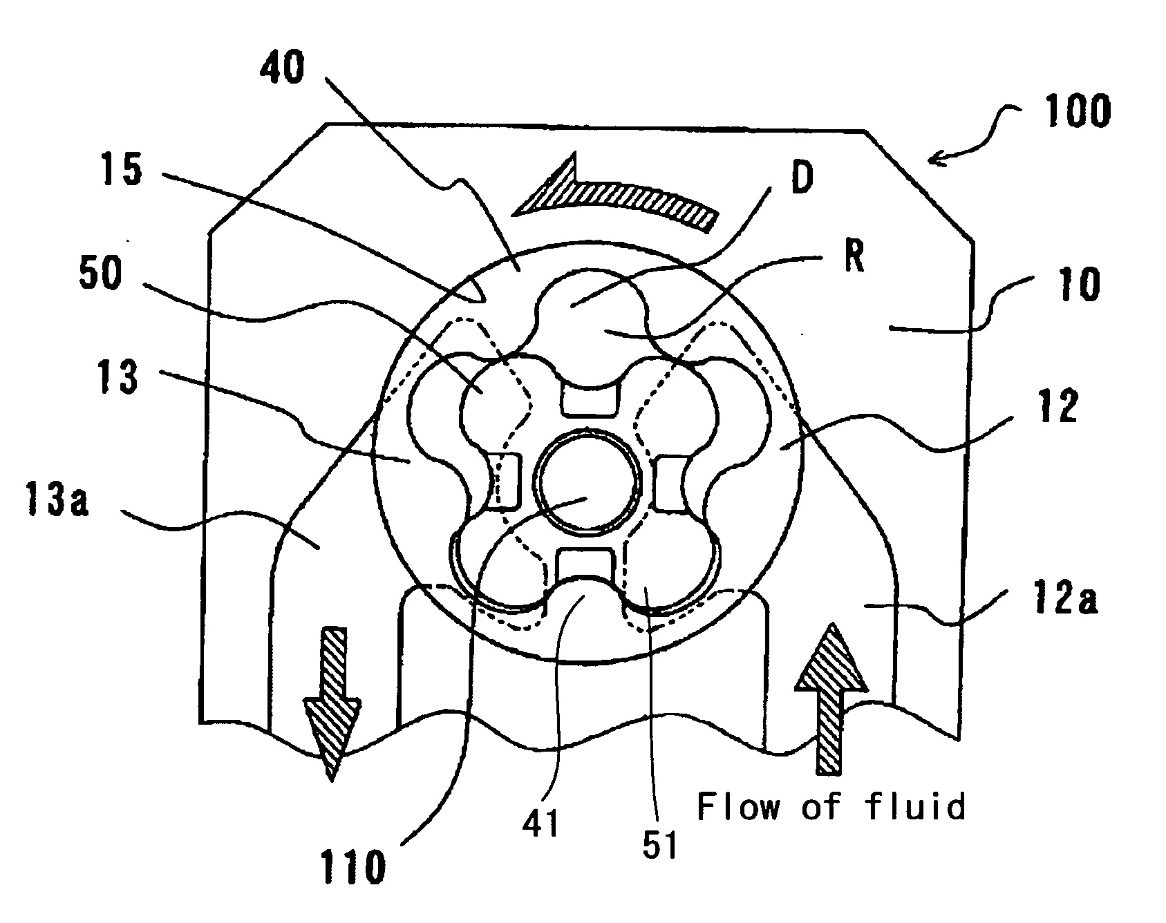
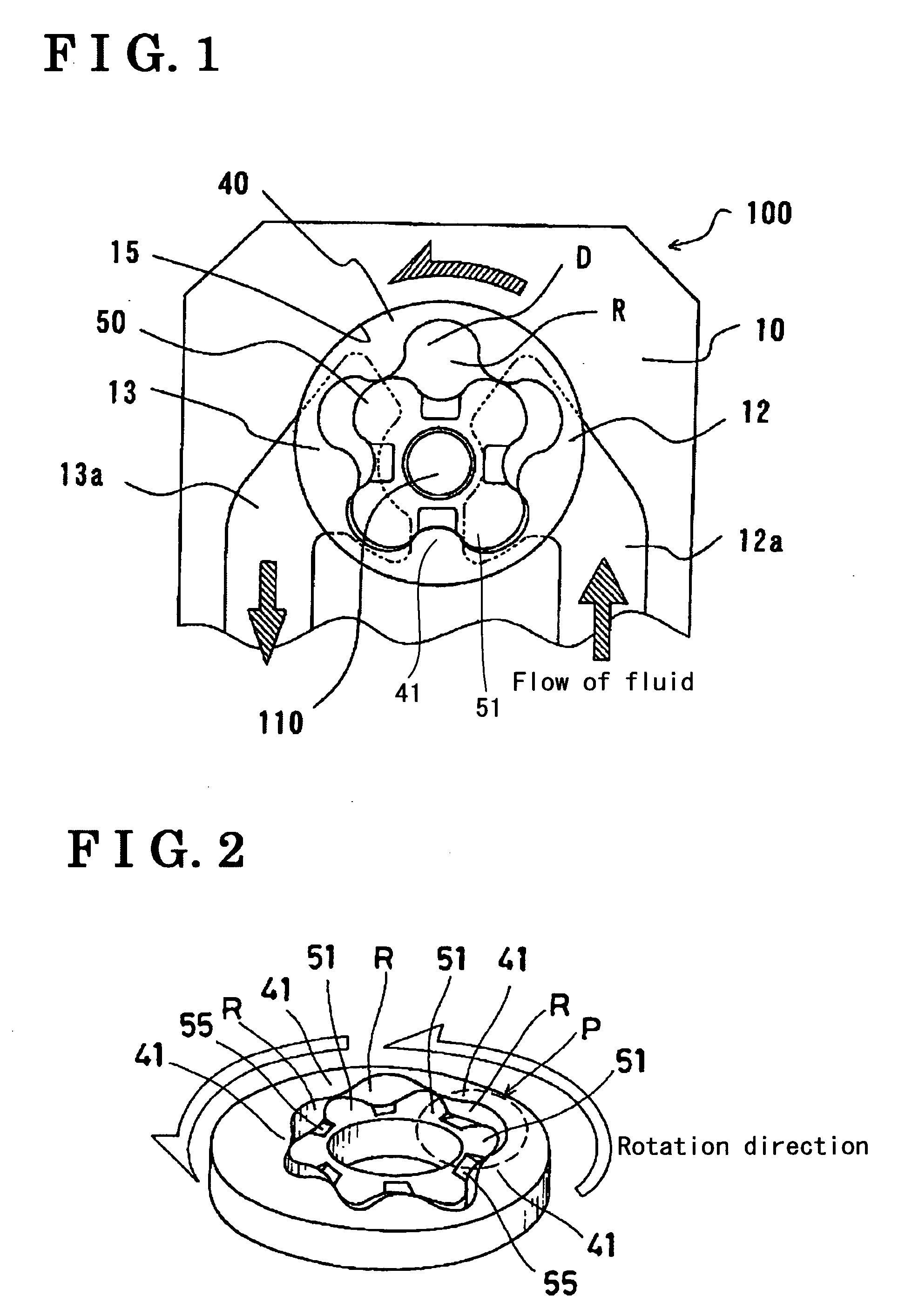
[0026]FIG. 1 is a backside view of a pump (i.e. inscribed gear pump) 100. The pump 100 mainly includes a body 10, a cover 20 (see FIG. 8), a driven rotor 40, a driving rotor 50, and a shaft 110 disposed into a center portion of the driving rotor 50 so as to drive the driving rotor 50. The body 10 and the cover 20 constitute a housing on which a rotor chamber 15 of a cylindrical space is formed. The rotor chamber 15 accommodates therein the driving rotor 50 into which the shaft 110 is disposed and the driven rotor 40 engaging with the driving rotor 50 in such a manner that the driven rotor 40 is off-centered relative to the driving rotor 50 by a predetermined amount. The driving rotor 50 and the driven rotor 40 engage with each other in such a manner that outer gears 51 of the driving rotor 50 and the inner gears 41 of the driven rotor 40 are respectively meshed with each other.

[0027]...


PUM


Abstract

An inscribed gear rotor includes a housing forming a cylindrical space, a driven rotor including a plurality of inner gears, a driving rotor including a plurality of outer gears engaging with the respective inner gears, a plurality of interspaces formed between the inner gears of the driven rotor and the outer gears of the driving rotor respectively, a volume of each of the interspaces being increased and decreased so as to complete one cycle in a rotation for the purposes of performing an intake and a discharge of fluid, an inlet port being in communication with the cylindrical space, an outlet port being in communication with the cylindrical space, and a groove formed on a side face of the driving rotor and being in communication with the inlet port and the at least one of the interspace.

Description

CROSS REFERENCE TO RELATED APPLICATIONS [0001] This application is based on and claims priority under 35 U.S.C. § 119 to Japanese Patent Application Nos. 2004-281843 and 2005-269894, filed on Sep. 28, 2004 and Sep. 16, 2005 respectively, the entire content of which is incorporated herein by reference. FIELD OF THE INVENTION [0002] This invention generally relates to a rotor structure of an inscribed gear pump. BACKGROUND [0003] In cases where a known inscribed gear pump widely used for an oil pump for a vehicle is utilized at a high rotational speed and then a suction speed of fluid is increased, suction of fluid in response to the rotational speed may not be achieved because of viscous resistance. Then, cavitation may be induced in an inlet passage (i.e. an inlet port and a space defined between rotor gears). The occurrence of cavitation may cause decrease of a pump volumetric efficiency, occurrence of abnormal noise, erosion inside of the pump, and the like. [0004] In order to avo...

Claims


Application Information

Patent Timeline
IPC IPC(8): F01C1/02F16N13/20F01C1/063F04C2/00
CPCF04C2/084F04C15/062F04C2/102
Inventor KIMURA, ICHIROKUROKAWA, HIROYUKI
Owner AISIN SEIKI KK
Why Eureka
Try Eureka