Intervertebral prosthesis

a technology for intervertebral bones and prostheses, applied in the field of intervertebral bones, can solve the problems of not optimally simulating the natural movement of the vertebral column, the intervertebral bones according to the state of the art exhibit a defect, etc., and achieve the effect of avoiding damage to the prosthetic end plates and distributing better

Inactive Publication Date: 2006-03-30
WEBER HELMUT
View PDF13 Cites 86 Cited by
  • Summary
  • Abstract
  • Description
  • Claims
  • Application Information

AI Technical Summary

Benefits of technology

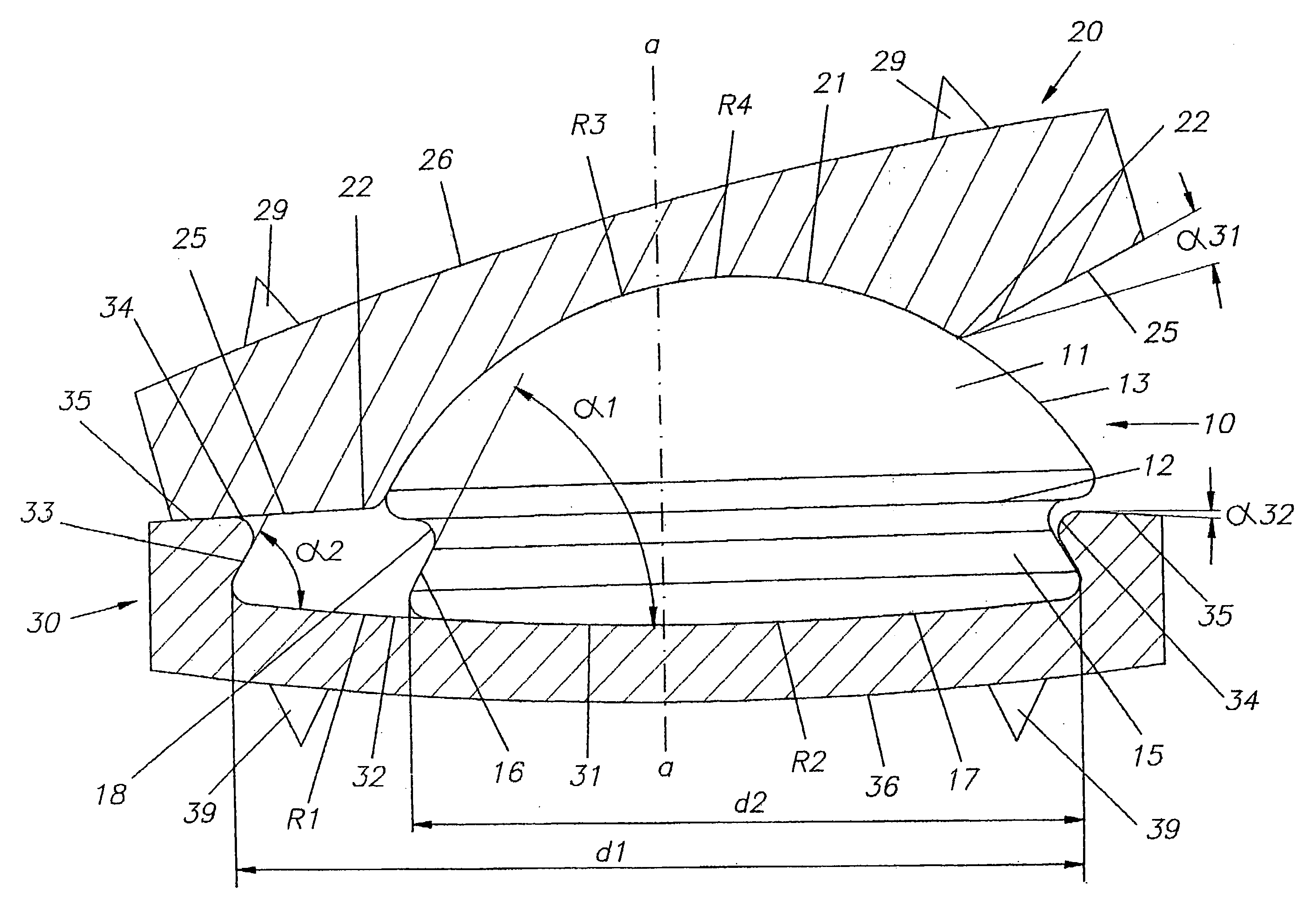
[0021] Preferably the surfaces of the two prosthetic end plates, beginning from the outer edge of the hemispherical shaped recess or, as the case may be, the essentially planar recess, are formed with an incline which decreases going outwards. Thus, in the case of a tilting of the two prosthetic end plates relative to each other, it can be achieved therewith, in t...

Problems solved by technology

The intervertebral prosthesis according to the state of the art thus exhibits...

Method used


Image

  • Intervertebral prosthesis
  • Intervertebral prosthesis
  • Intervertebral prosthesis

Examples


Embodiment Construction

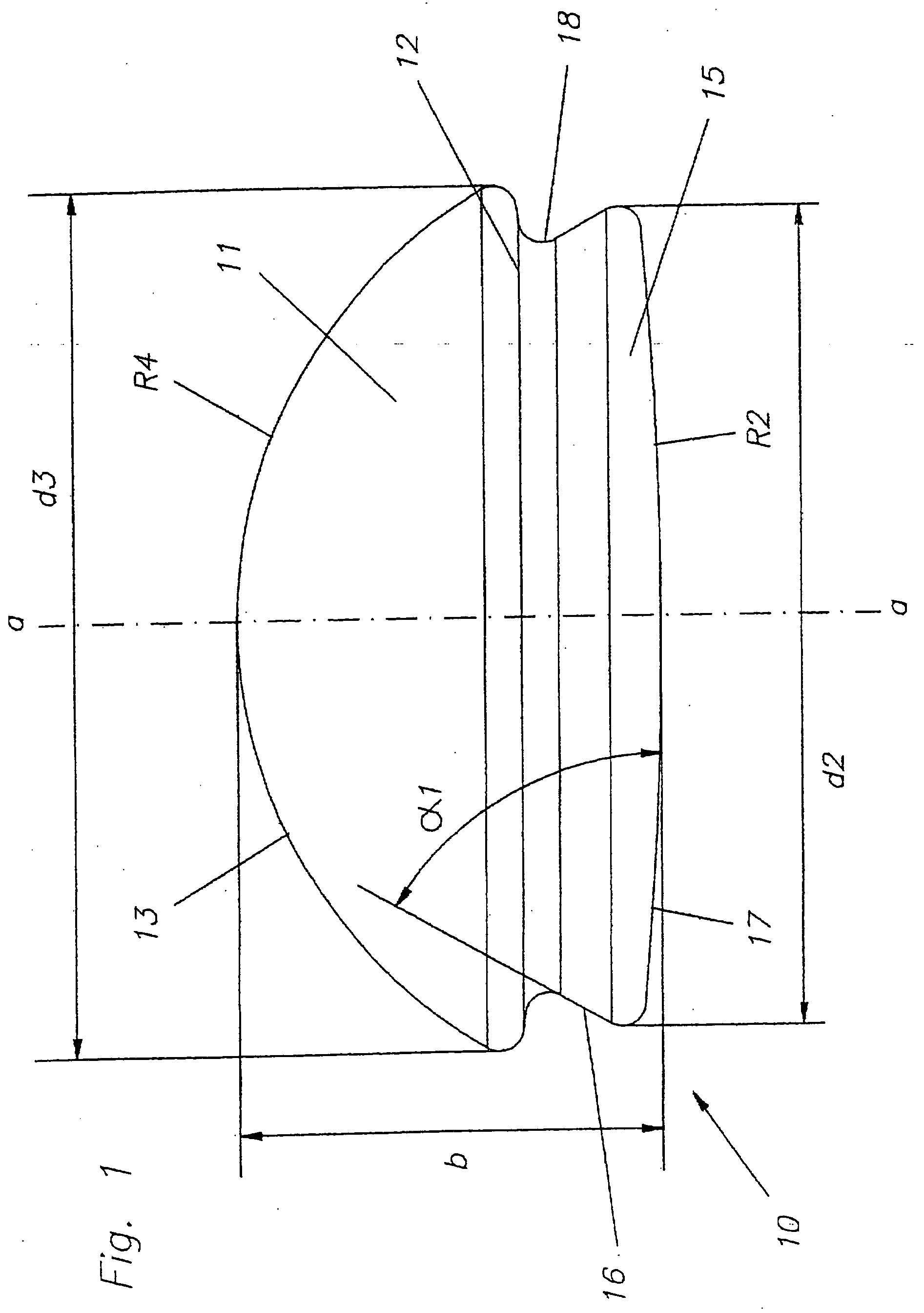
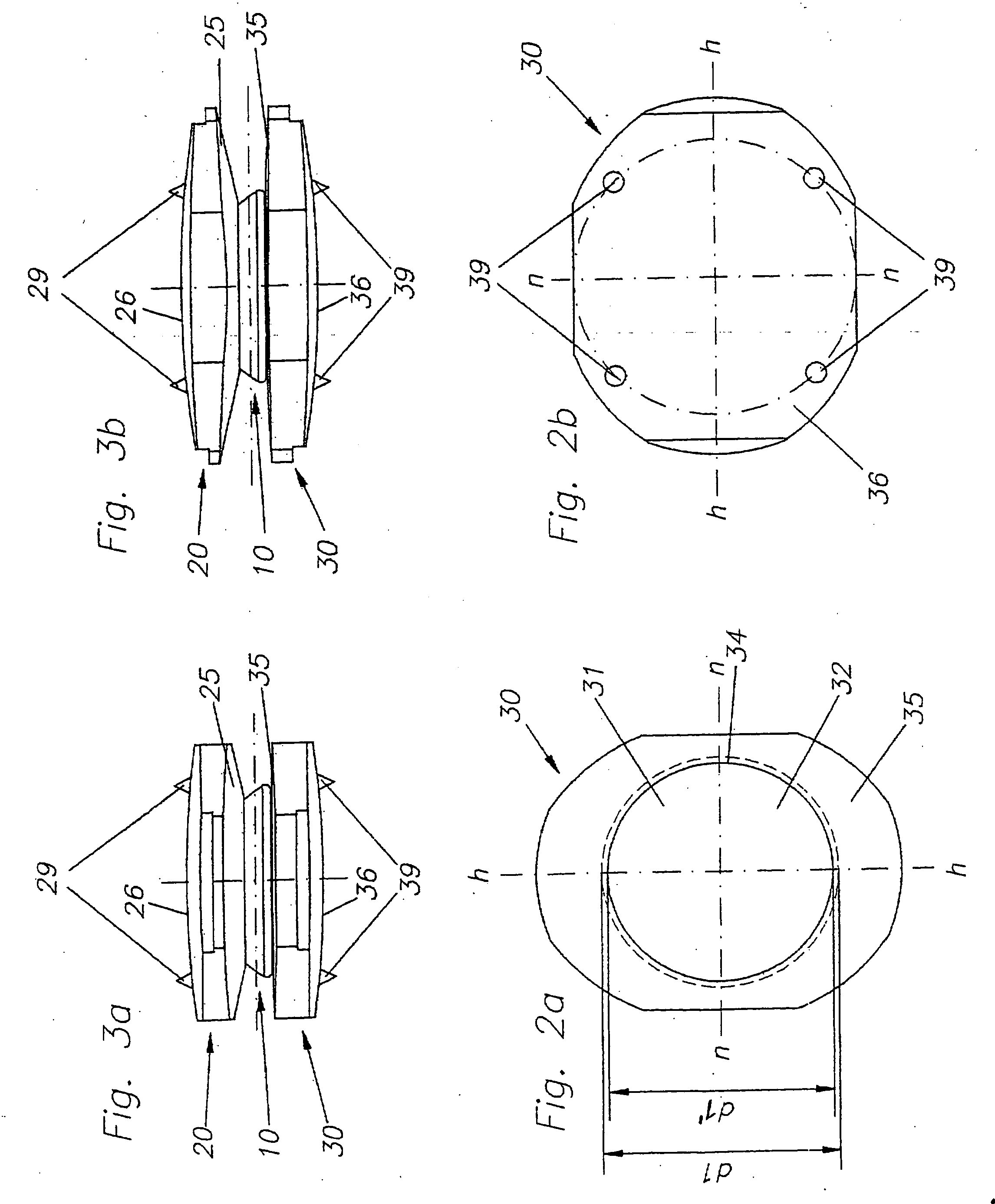
[0041]FIG. 1 shows a side view of a prosthetic core 10 according to the invention. The prosthetic core 10 has a hemispherical segment 11 with a curved surface 13 and a planar surface 12. The hemispherical surface 11 is defined by a radius R4. The planar surface 12 of the hemispherical segment 11 has a diameter d3, which corresponds to the greatest radial circumference or dimension of the prosthetic core 10.

[0042] Connected to the planar surface 12 of the hemispherical segment 11 is a substantially flat segment 15. The flat segment 15 has an essentially circular cross-section with a diameter d2. The result is a rotational-symmetric prosthetic core 10. The rotation axis of the prosthetic core 10 is shown in FIG. 1.

[0043] The flat segment 15 can have a rectangular or square cross-section, wherein however such a design of the prosthetic core 10 provides less than optimal simulation results of the intervertebral prosthesis, since such a prosthetic core 10 cannot freely rotate.

[0044] T...


PUM


Abstract

The invention concerns an intervertebral prosthesis comprised of a first prosthetic end plate (20) and a second prosthetic end plate (30) as wall as a prosthetic core (10) located between the first prosthetic end plate (20) and the second prosthetic end plate (30), wherein the first prosthetic end plate (20) has a hemispherical shaped recess (21) with a radius (R3), in which a hemispherical segment (11) of the prosthetic core (10) engages, and wherein the second prosthetic end plate (30) has an essentially planar recess (31), in which an essentially flat segment (15) of the prosthetic core (10), connected to the hemispherical segment (11), engages, wherein the essentially flat segment (15) of the prosthetic core (10) is slideably moveable in the essentially planar recess (31).

Description

BACKGROUND OF THE INVENTION [0001] 1. Field of the Invention [0002] The invention concerns an intervertebral prosthesis according to the precharacterizing portion of Patent Claim 1. [0003] 2. Description of the Related Art [0004] Three-part intervertebral prosthesis are known, for example from EP 0 176 728 A1 or WO 02 / 08018 A1, comprised of two prosthetic end plates or cover plates, between which a prosthetic core is provided. The prosthetic end plates are comprised of a circular shaped or elliptical shaped disk, which exhibits a hemispherical recess on one side. The prosthetic core is in the shape of a circular disk, exhibiting on both sides respectively an axially disposed hemispherical segment and, running around the outer edge, an axially projecting ring segment. In the assembled condition of the intervertebral prosthesis the hemispherical segments of the prosthetic core lie in the hemispherical recesses of the two prosthetic end plates. [0005] If the intervertebral prosthesis i...

Claims


Application Information

Patent Timeline
IPC IPC(8): A61F2/44
CPCA61F2/4425A61F2002/30113A61F2002/30133A61F2002/30563A61F2002/30616A61F2002/30649A61F2310/00023A61F2002/30841A61F2002/443A61F2230/0006A61F2230/0015A61F2310/00017A61F2002/30662
Inventor WEBER, HELMUT
Owner WEBER HELMUT
Why Eureka
Try Eureka