
Glass door

a glass door and glass technology, applied in the field of glass doors, can solve the problems of troublesome whole procedure for assembling glass doors, time-consuming, and inability to adjust, and achieve the effect of easy and reliable assembly

Inactive Publication Date: 2006-04-06
CHEN YUNG FUNG +2
View PDF5 Cites 44 Cited by
  • Summary
  • Abstract
  • Description
  • Claims
  • Application Information

AI Technical Summary

Benefits of technology

[0008] A bolt extends through the through-hole of the outer clamping member and the screw hole of the inner clamping member. When the bolt is turned, the inner clamping member is moved such that the limbs of the inner clamping member are moved toward each other to tightly clamp the associated end of the pane of glass or away from each other. The glass door in accordance with the present invention can be assembled easily and reliably without the need of adhesive and silicon rubber. If necessary, adjustment can be carried out during the assembling procedure.
[0009] Each inner face of each limb of the inner clamping member includes a serrated section to assist in secure engagement between the lining member and the associated side of the pane of glass.

Problems solved by technology

The whole procedure for assembling the glass door is troublesome and time-consuming.
Further, adjustment is not allowed when any mistake is made during the assembling procedure.

Method used


Image

  • Glass door
  • Glass door
  • Glass door

Examples


Embodiment Construction

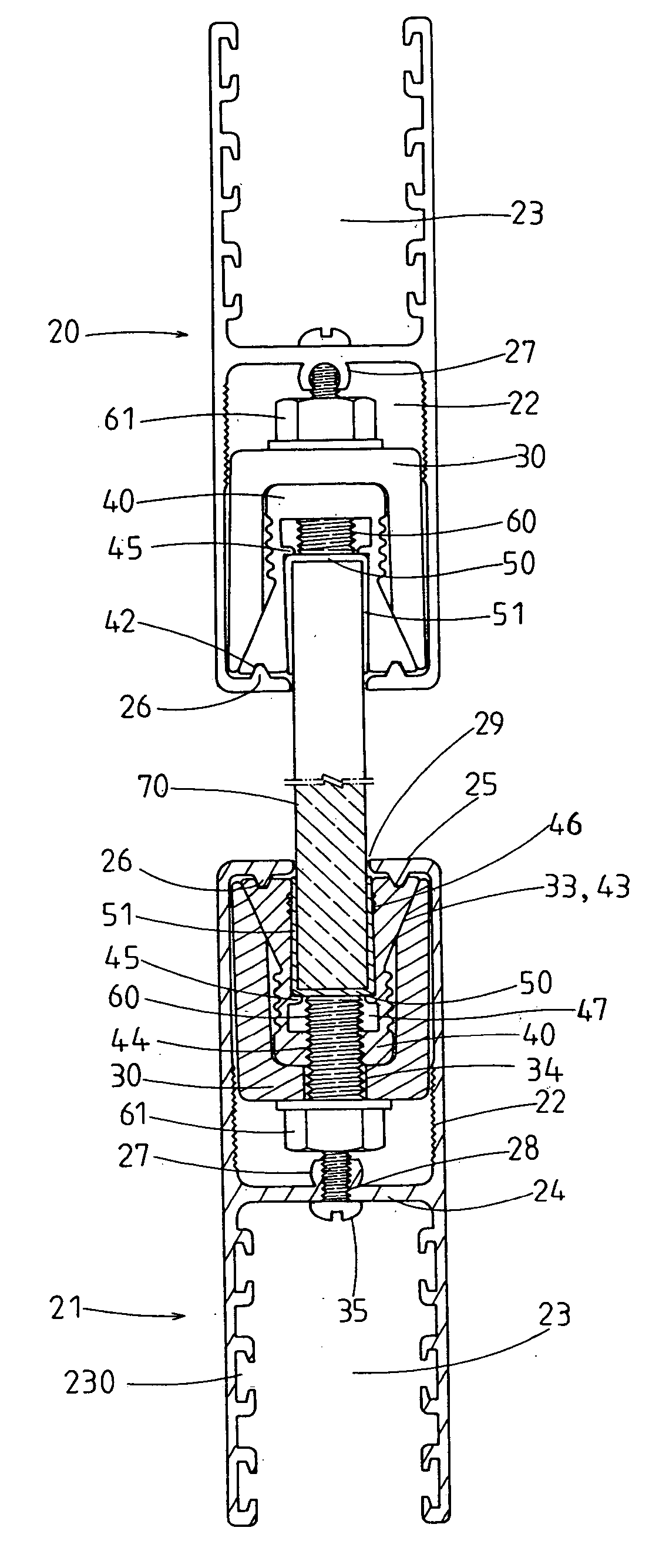
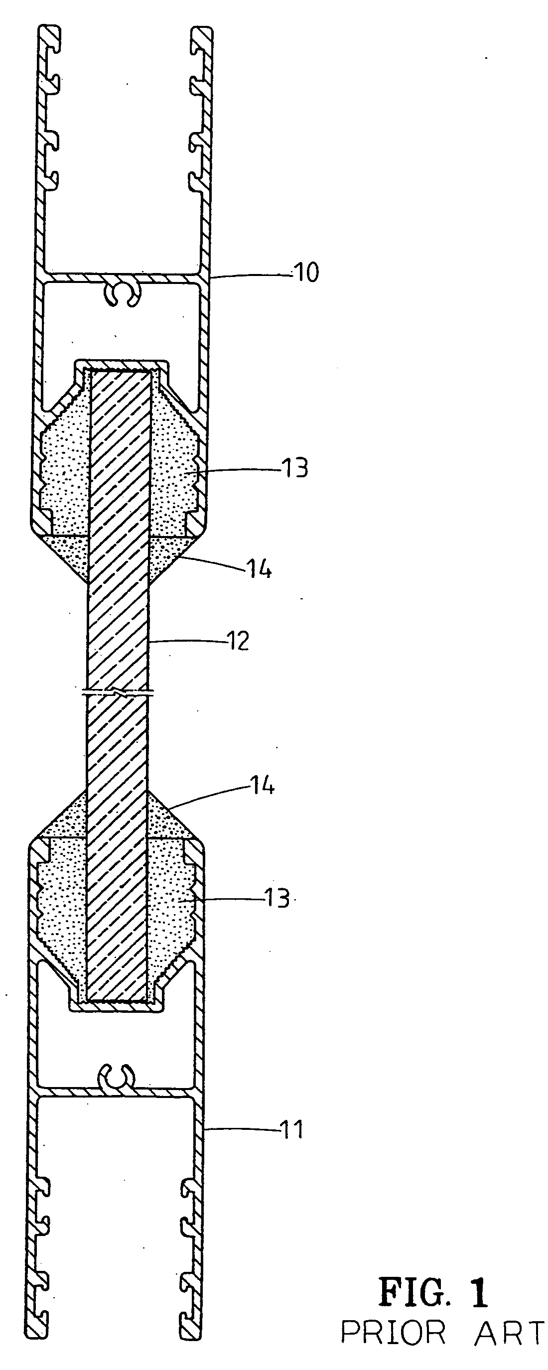
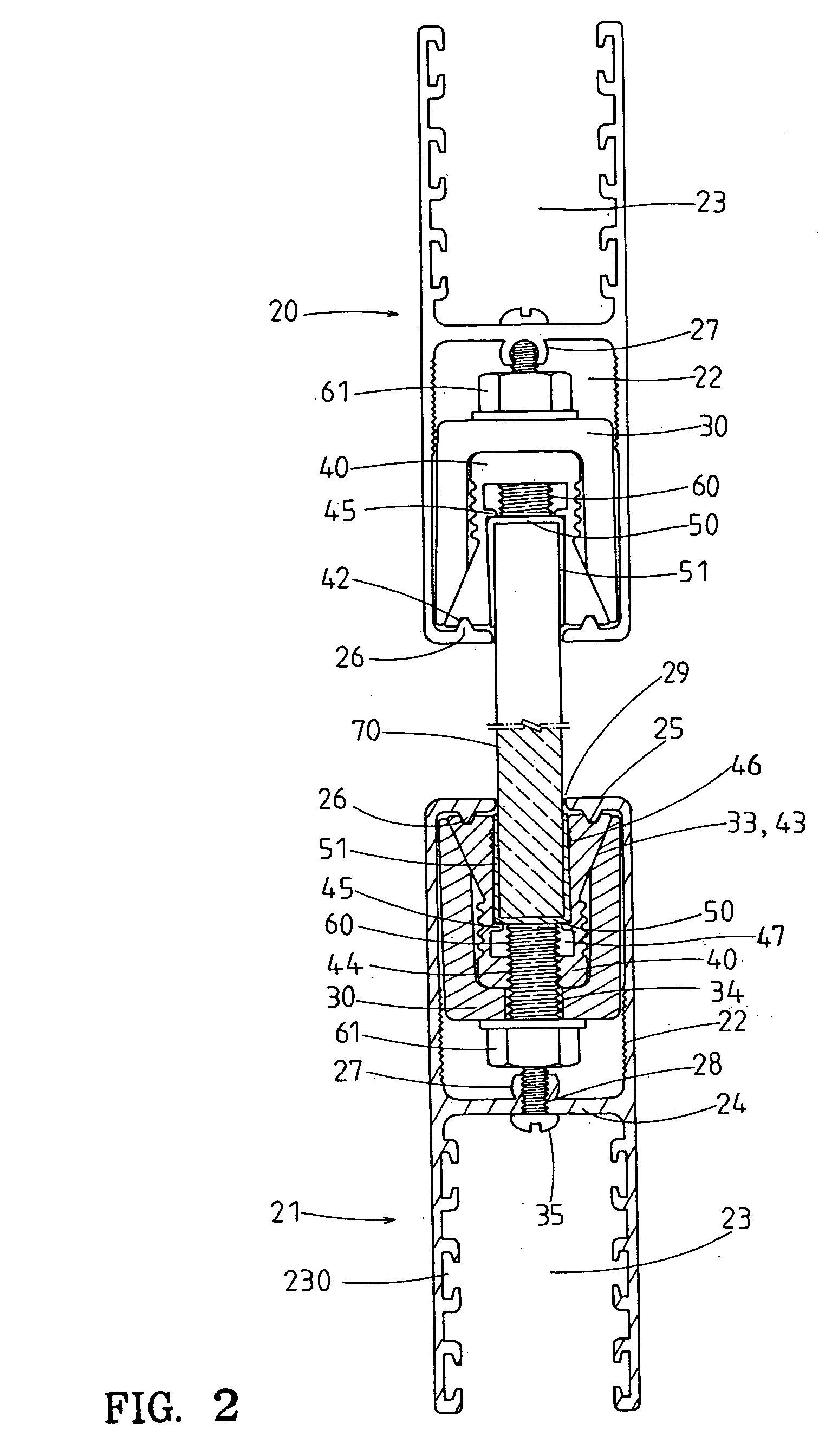
[0024] Referring to FIG. 1, a glass door in accordance with the present invention comprises an upper frame 20, a lower frame 21, and a pane of glass 70 mounted between the upper frame 20 and the lower frame 21. Two clamping devices are provided for respectively fixing upper and lower ends of the pane of glass 70 to a lower of the upper frame 20 and an upper end of the lower frame 21. Each clamping device includes an outer clamping member 30, an inner clamping member 40, and a lining member 50. Coupling of the upper end of the pane of glass 70 to the lower end of the upper frame 20 by one of the clamping devices is identical to coupling of the lower end of the pane of glass 70 to the upper end of the lower frame 21 by the other clamping device. Further, the lower end of the upper frame 20 and the upper end of the lower frame 21 are symmetrically constructed. Thus, only coupling of the lower end of the pane of glass 70 to the upper end of the lower frame 21 is disclosed hereinafter.

[...


PUM


Abstract

A glass door includes a pane of glass securely held by upper and lower frames. A clamping device is mounted in an outer groove of each frame and includes an outer clamping member mounted in the outer groove and an inner clamping member mounted in the outer clamping member. Each of two limbs of the inner clamping member includes an inclined outer face abutting against an inwardly facing inclined face of an associated limb of the outer clamping member. A lining member is sandwiched between an associated end of the pane of glass and inner faces of the limbs of the inner clamping member. A bolt extends through the outer clamping member and the inner clamping member. When the bolt is turned, the limbs of the inner clamping member are moved toward each other to tightly clamp the associated end of the pane of glass or away from each other.

Description

BACKGROUND OF THE INVENTION [0001] 1. Field of the Invention [0002] The present invention relates to a glass door. In particular, the present invention relates to a glass door that is easy to assemble. [0003] 2. Description of the Related Art [0004] A typical glass door includes a pane of glass 12 mounted between an upper frame 10 and a lower frame 11, as illustrated in FIG. 1 of the drawings. In assembly, a lower end of the pane of glass 12 is mounted into a groove (not labeled) in the lower frame 11 and adhesive 13 is then poured into the groove of the lower frame 11. After fixing of the lower end of the pane of glass 12 in the lower frame 11, an upper end of the pane of glass 12 is mounted into a groove (not labeled) in the upper frame 10 and adhesive 13 is then poured into the groove of the upper frame 10. After fixing of the upper end of the pane of the glass 12 in the upper frame 10, silicon rubber 14 is applied to seal the upper end face of the lower frame 11 and the lower en...

Claims


Application Information

Patent Timeline
Patent Type & Authority Applications(United States)
IPC IPC(8): E06B3/00E06B3/964
CPCE06B3/02E06B3/5454
Inventor CHEN, YUNG-FUNGYANG, YEN-HWANGCHANG, PAO-LOU
Owner CHEN YUNG FUNG
Learn More