
Tool with signal generator

a signal generator and tool technology, applied in the field of tools, can solve the problems of incorrect tightening of screws, operating distraction, and failure to correctly understand the signal transmitted, so as to reduce the error frequency in the operation of the tool and in the production of the connection

Inactive Publication Date: 2006-04-06
BOSCH REXROTH AG
View PDF8 Cites 15 Cited by
  • Summary
  • Abstract
  • Description
  • Claims
  • Application Information

AI Technical Summary

Benefits of technology

"The present invention is a tool that reduces errors in operation and production of connections by providing a response signal to an operator in the form of an acoustic, tactile, or optical signal. The signal generator is placed on the tool or inside it, and it indicates the progress of a work procedure or parts of it. The tool can be any type of industrial tool used by an operator, and the signal generator can be a module that can be easily installed or replaced. The invention helps to improve the operator's focus and reduces distraction or inattention, resulting in improved efficiency and accuracy in the work procedure."

Problems solved by technology

Frequently, however, operators are distracted and do not correctly understand the signal transmitted, are irritated by the jolt of the tool switching off, and wrongly assume that the screw has been correctly tightened.
This can also be caused by distraction or inattention and consequently, not every screw connection is tightened to the correct torque.
The dangerous result: insufficiently secured connections, e.g. wheels of commercial or passenger vehicles.

Method used


Image

  • Tool with signal generator
  • Tool with signal generator

Examples


Embodiment Construction

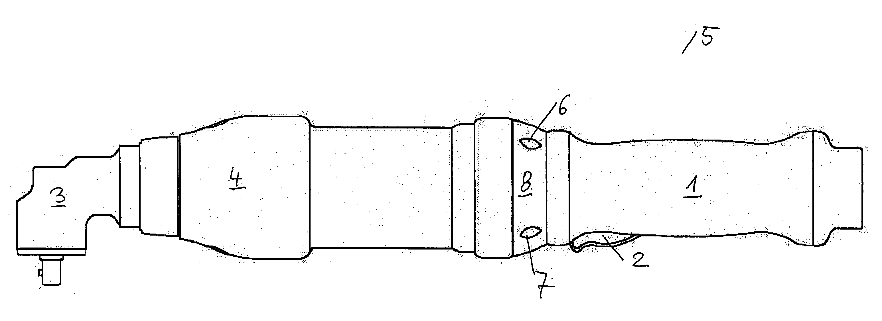
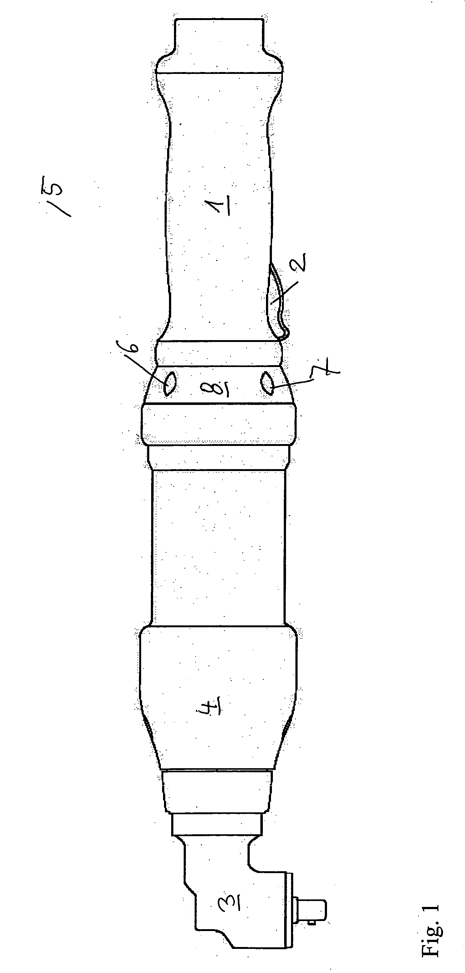
[0019]FIG. 1 shows an electric hand screwdriver 5 as an exemplary embodiment form of the current invention. The hand screwdriver 5 has a handle 1, an actuating lever 2, an output 3, and a housing 4 on which the output 3 is situated, oriented at right angles. The drawing also shows two lights 6, 7 on a middle part 8.

[0020] The tool is a screwdriver 5 with light signal generators formed by the lights. The housing 4 and / or handle 1 of the tool also contains a device for generating an acoustic and / or tactile response signal that makes it possible to signal a completed screw driving procedure or completed parts of a screw driving procedure. If the red light 6 comes on, this indicates that the work procedure is not yet complete. If the green light 7 comes on, this indicates that the work procedure has been completed.

[0021] The acoustic and tactile signal generator in the housing 4 generates a pulsating signal whose characteristic signal values can be set by the operator. The tactile sig...


PUM

PropertyMeasurementUnit
circumferenceaaaaaaaaaa
torqueaaaaaaaaaa
frequencyaaaaaaaaaa

Abstract

A tool has a tool part for producing a connection, and a signal generator generating a signal such that the tool part gives an operator a response signal regarding a progress of a work procedure, which response signal can be of acoustic nature and / or a tactile nature, and indicating a completed work procedure or completed parts of the work procedure, wherein the signal generator is arranged on the tool part or contained inside the tool part.

Description

BACKGROUND OF THE INVENTION [0001] The present invention relates to the general class of tools for producing detachable or nondetachable connections. [0002] As a rule, visual displays are used to furnish tool operators with information about the current state of the work procedure being performed with the tool. For example, there are screwdrivers currently on the market that have red and green lights on the circumference of their housing in order to signal a result of the screw driving procedure. [0003] The operator must therefore keep the tool constantly in view in order to correctly register the transmitted information. Frequently, however, operators are distracted and do not correctly understand the signal transmitted, are irritated by the jolt of the tool switching off, and wrongly assume that the screw has been correctly tightened. This can also be caused by distraction or inattention and consequently, not every screw connection is tightened to the correct torque. The dangerous...

Claims


Application Information

Patent Timeline
Patent Type & Authority Applications(United States)
IPC IPC(8): B25B23/145
CPCB25B21/00B25B23/147B21J15/28B23K11/25
Inventor KUGLER, ACHIM
Owner BOSCH REXROTH AG
Learn More