Recoil starter

a starter and coil technology, applied in the direction of engine starters, muscle operated starters, machines/engines, etc., can solve the problems of spoiled durability and broken damper springs, and achieve the effects of reducing weight, preventing breakage of damper springs, and improving durability of damper springs

Active Publication Date: 2006-04-06
STARTING IND CO LTD
View PDF8 Cites 23 Cited by
  • Summary
  • Abstract
  • Description
  • Claims
  • Application Information

AI Technical Summary

Benefits of technology

[0012] According to the recoil starter of the first aspect of the invention, in which the rotation of the rope reel is transmitted to the cam member via the coil spring-like damper spring engaged at both ends thereof with the rope reel and cam member, either one of the rope reel and cam member being provided with a boss portion the length of which is substantially equal to that of the wound portion of the damper spring, the inner circumferential portion of substantially the whole length of the damper spring being supported on the boss portion, the wound portion of substantially the whole length thereof being formed so that the wound portion of substantially the whole length thereof is wound tightly around the outer circumferential surface of the boss portion when the damper spring is elastically deformed due to the starting resistance of the engine, so that the damper spring of substantially the whole length thereof is wound tightly around the outer circumferential surface of the boss portion made of a single member, this preventing the occurrence of the entry of a part of the damper spring into the clearance between the boss portions and the resultant one-sided deformation of the damper spring, and the occurrence of great deformation of only the central portion of the damper spring and the breakage of the damper spring, so that the durability of the damper spring can be improved.
[0013] According to the second aspect of the invention, the cross-sectional shape of the wire material of which the damper spring is formed is set to a cross-sectional shape having at least one linear side, this wire material being wound so that the linear portion becomes the inner circumferential surface thereof to thereby form a coil spring-like damper spring, the inner side surface of the damper spring being thereby wound tightly in a large area around the outer circumferential surface of the boss portion, so that an impression of the damper spring is not left on the boss portion even when the damper spring is wound tightly around the outer circumferential surface of the boss portion formed on the rope reel or cam member due to an excessively large load occurring in the engine. Since the cross-sectional area of the wire material can be set larger than that of the wire material used in the related art recoil starter without increasing the size of the wire material in the direction of the thickness thereof, a damper spring of a larger elastic force can be formed without rendering the size of the whole of the damper spring larger. Furthermore, when the elastic force is unchanged, the number of winding is increased to enable a rotational force of a large angle of rotation to be accumulated. Therefore, a damper spring of a large elastic force and a damper spring of a high power accumulating capability of a larger angle of rotation can be held in a case of the same outer sizes. When the damper spring is a damper spring of the power accumulating capability of the same elastic force and the same angle of rotation, the recoil starter can be further miniaturized and weight-reduced.
[0014] According to the third aspect of the invention, the boss portion is formed on the side surface of the rope reel which is opposed to the cam member so that the boss portion is integral with the rope reel, and the wound portion of substantially the whole length of the damper spring is thereby wound tightly around the outer circumferential surface of the boss portion. Therefore, the occurrence of one-sided deformation of the damper spring due to the entry of a part thereof into a clearance between the boss portions, or the great deformation of only the central portion of the damper spring can be prevented, and the breakage of the damper spring is thereby prevented, so that the durability of the damper spring can be improved.
[0015] According to the fourth aspect of the invention, the boss portion is formed on the side surface of the cam member which is opposed to the rope reel so that the boss portion is integral with the cam member, and the damper spring of substantially the whole length is thereby wound tightly around the outer circumferential surface of the boss portion formed on the side surface of the cam member. Therefore, the occurrence of one-sided deformation of the damper spring due to the entry of a part of the damper spring into a clearance between the boss portions, or the great deformation of only the central portion of the damper spring is prevented, and the breakage of the damper spring is prevented, so that the durability of the damper spring can improved.

Problems solved by technology

When the rope reel and cam member in this condition are relatively rotated, only the central portion of the damper spring that is near the abutted surface of the two boss portions is greatly deformed to cause in some cases the damper spring to be broken, or the durability thereof to be spoiled.

Method used


Image

  • Recoil starter
  • Recoil starter
  • Recoil starter

Examples


second embodiment

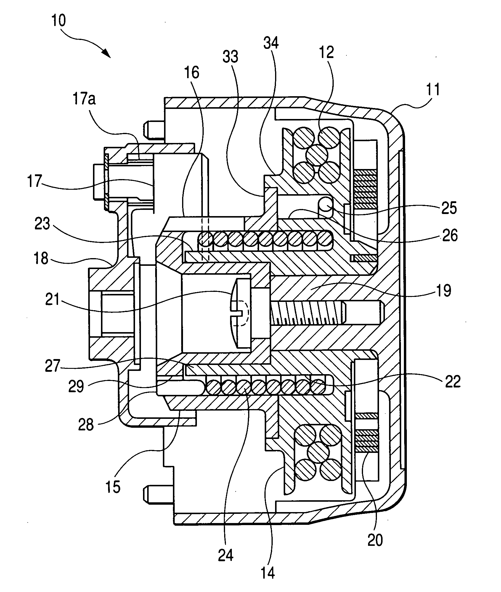
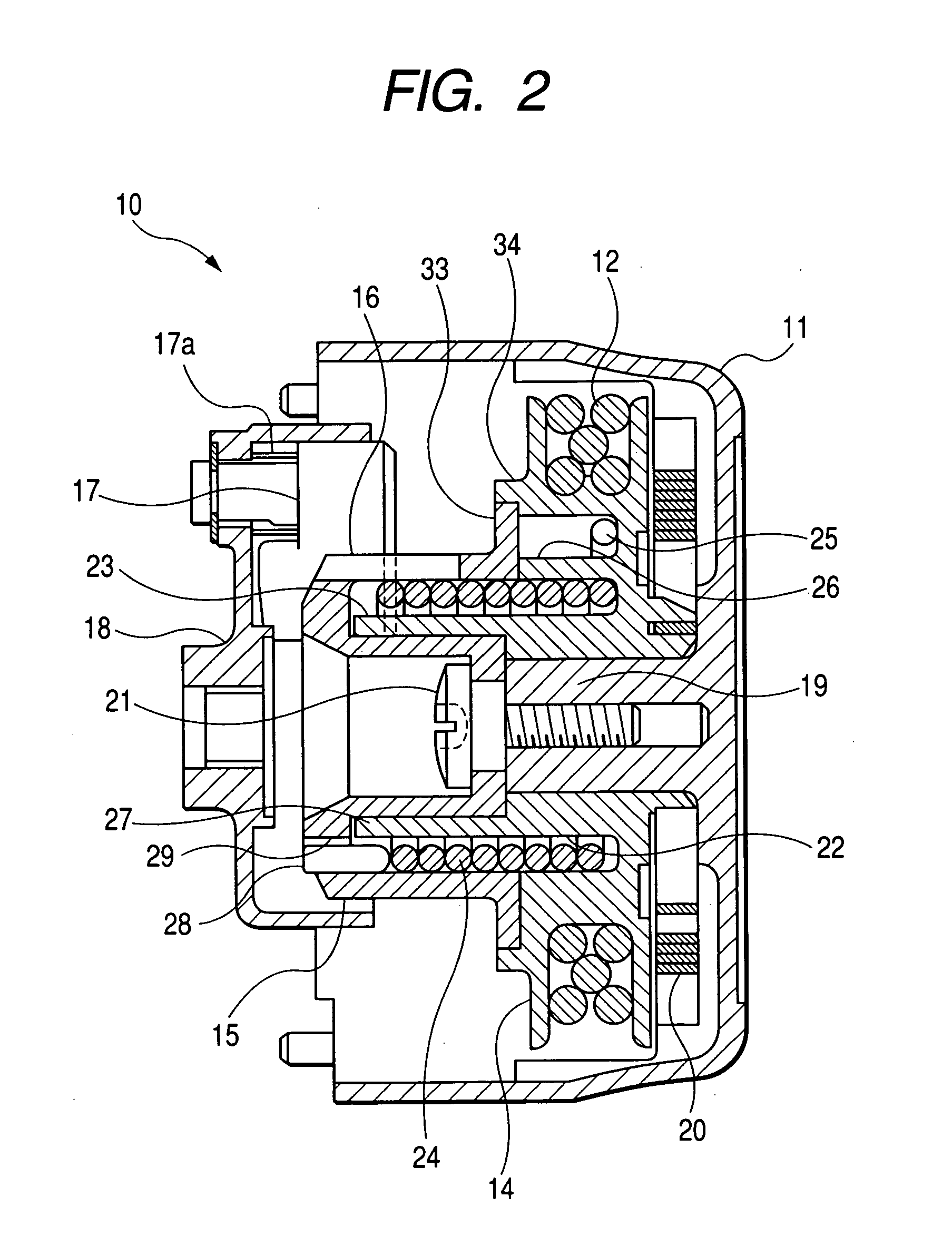
[0042]FIG. 6 shows a recoil starter 40 in the present invention. In the recoil starter 40 in this embodiment, a boss portion 41 for supporting a wound portion of its substantially whole length of the damper spring 24 from the inner side thereof is formed on a cam member 15. As shown in FIG. 6, the side surface of the cam member 15 which is opposed to a rope reel 14 is provided with an annular recess 42 opened toward the rope reel 14. An inner side portion of this annular recess 42 is projected toward the rope reel 14 and forms a cylindrical boss portion 41 around the outer circumferential surface of which the damper spring 24 is fitted. One end side of the wound portion of the damper spring 24 is held in the annular recess 42, and an engagement end portion 28 formed so as to extend axially at one end side of the damper spring 24 is inserted through an engagement hole 29 formed so as to extend from a bottom portion of the annular recess 42 to an upper surface of the cam member 15. Th...

first embodiment

[0048] In the recoil starter 50 in this embodiment, the projection 55 formed on the ratchet claws 52 rotatably held on the cam member 15 is loosely fitted in a guide recess 56 formed in the guide plate 53 to which a predetermined level of rotational resistance is given with respect to a reel support shaft 19. A ratchet mechanism 51 adapted to frictionally operate the ratchet claws 52 by the rotational operation of the cam member 15 is formed between the cam member 15 and rotary member 18. Owing to this arrangement, the damper spring 4 of the whole length is wound tightly around an outer circumferential surface of the boss portion 41. This enables a recoil starter of a static sound, which is capable of prolonging the durability of the damper spring 24, and which is capable of preventing the occurrence of intermittent sounds and the like of the ratchet claws 52, to be provided. The boss portion 41 in this embodiment is formed so as to project from the cam member 15 toward the rope ree...


PUM


Abstract

A coil starter formed so that the rotation of a rope reel is transmitted to a cam member via a coil spring-like damper spring both ends of which are engaged with the rope reel and cam member respectively, wherein the rope reel or cam member is provided with a boss portion the length of which is substantially equal to that of a wound portion of the damper spring, the inner circumferential side of substantially the whole length of the damper spring being supported on the boss portion, the wound portion of substantially the whole length of the damper spring being thereby wound uniformly and tightly around the outer circumferential surface of the boss portion when the damper spring is elastically deformed due to the engine starting resistance.

Description

BACKGROUND OF THE INVENTION [0001] 1. Field of the Invention [0002] The present invention relates to a recoil starter adapted to rotate a rope reel by drawing an end of a recoil rope wound around the rope reel and drawn to the outside of a recoil rope case, transmit the rotation of the rope reel to a cam member via a damper spring, transmit the rotation of the cam member to an engine via a ratchet mechanism, and thereby start the engine. [0003] 2. Description of the Related Art [0004] A recoil starter has already been known which is adapted to rotate a rope reel, around which a recoil rope is wound, by drawing the recoil rope, rotate a rotary member of an engine connected to a cam member, which is driven by the rope reel, via a ratchet mechanism, and thereby start the engine, wherein a damper spring wound like a return coil spring is interposed between the rope reel and cam member, the damper spring elastically connecting in the rotational direction the rope reel and cam member toge...

Claims


Application Information

Patent Timeline
Patent Type & Authority Applications(United States)
IPC IPC(8): F02N3/02
CPCF02N3/02F02N5/02F02N15/027
Inventor HORIKOSHI, YOSHINORI
Owner STARTING IND CO LTD
Why Eureka
Try Eureka