Heddle frame

a frame and sleeve technology, applied in the direction of shedding mechanism, dobbie, textiles and paper, etc., can solve the problems of buckling, damage to the groove or bore through which they extend, limited access to coupling devices, etc., to prevent lateral vibration of the drive rod and prevent damage to the material comprising

Inactive Publication Date: 2006-04-06
GROZ BECKERT KG
View PDF12 Cites 6 Cited by
  • Summary
  • Abstract
  • Description
  • Claims
  • Application Information

AI Technical Summary

Benefits of technology

[0008] This object is attained by the heddle frame having the characteristics of claim 1. This heddle frame has two lateral sampsons, in which an intermediate layer is located between the drive rods and the corresponding channel of the lateral sampson. The intermediate layer limits the space available laterally next to the drive rod and thus prevents the drive rod from buckling laterally under a pressure load and also prevents lateral vibration of the drive rod. Direct contact is also prevented between the lateral sampson and the drive rod, thus preventing damage to the material comprising the lateral sampson. The intermediate layer preferably comprises a permanent-elastic plastic, such as polyamide, or rubber.

Problems solved by technology

The accessibility of the coupling devices is limited.
The buckling occurs especially under load, because of the strong compressive forces acting on the drive rods.
These forces can damage the groove or bore through which they extend.
Such damage consequently rapidly causes failure of the lateral sampsons, which break.
The damage reduces the already low fatigue strength of the lateral sampsons, which typically or of aluminum.

Method used


Image

  • Heddle frame
  • Heddle frame
  • Heddle frame

Examples


Embodiment Construction

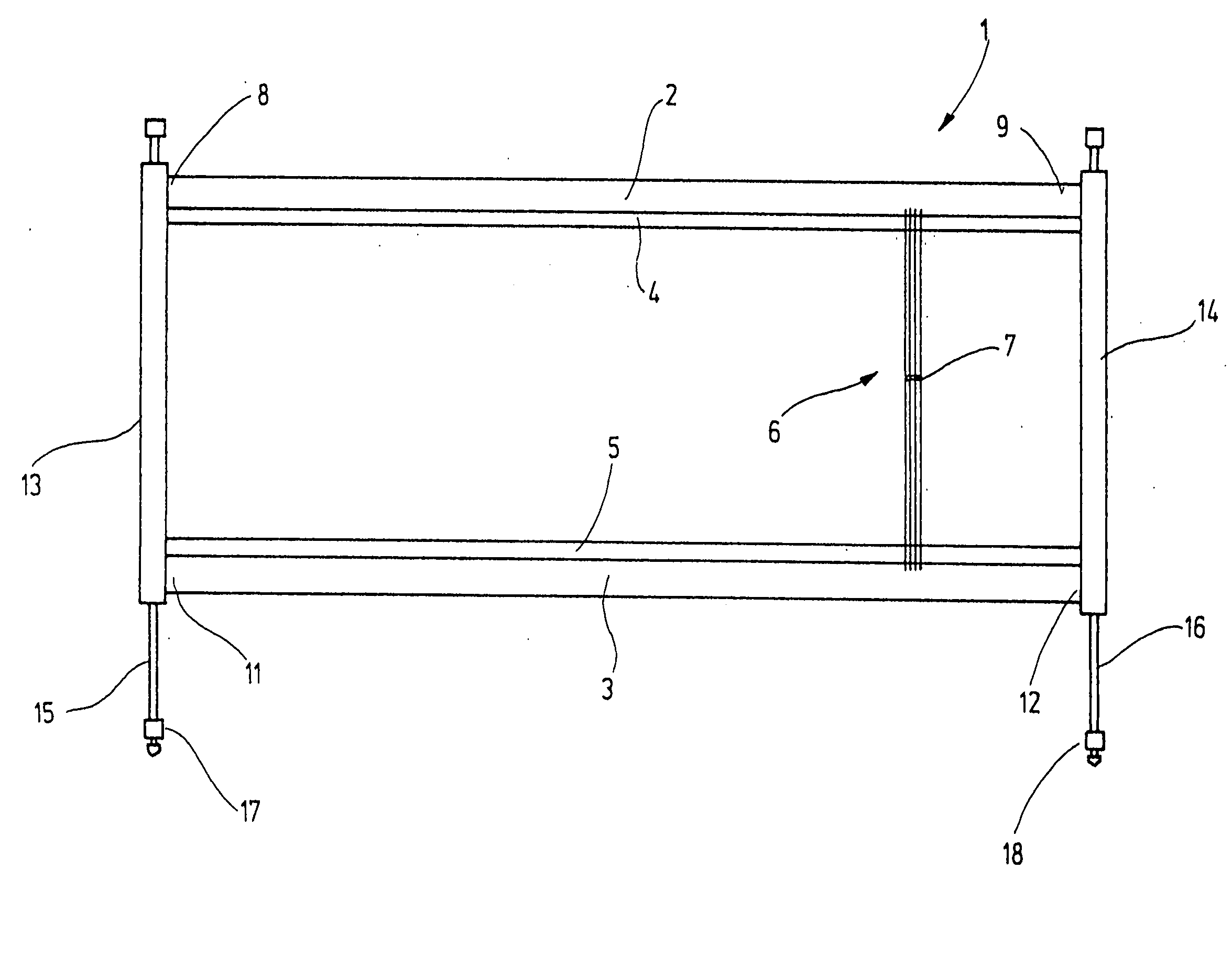
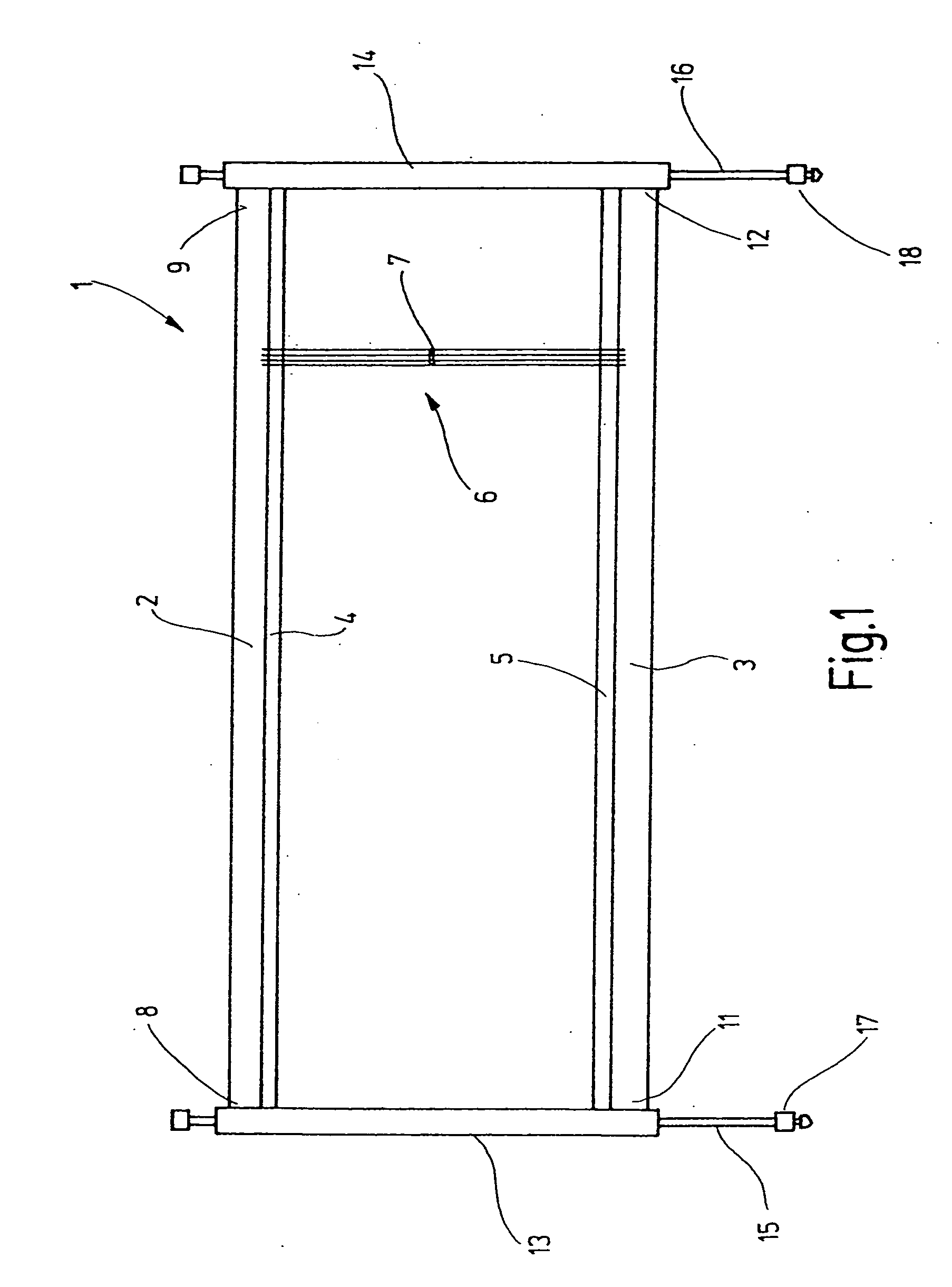
[0024] In FIG. 1, a heddle frame 1 is shown that is intended for a high-speed power loom. The heddle frame includes frame rods 2, 3, which are embodied for instance as hollow aluminum profile sections. Supported on them are steel support rails 4, 5, on which heddles 6 are seated. The heddles each have an eyelet 7 for a warp yarn. With the heddle frame 1, the warp yams are moved upward and downward out of the warp yarn plane, in order to open and close sheds.

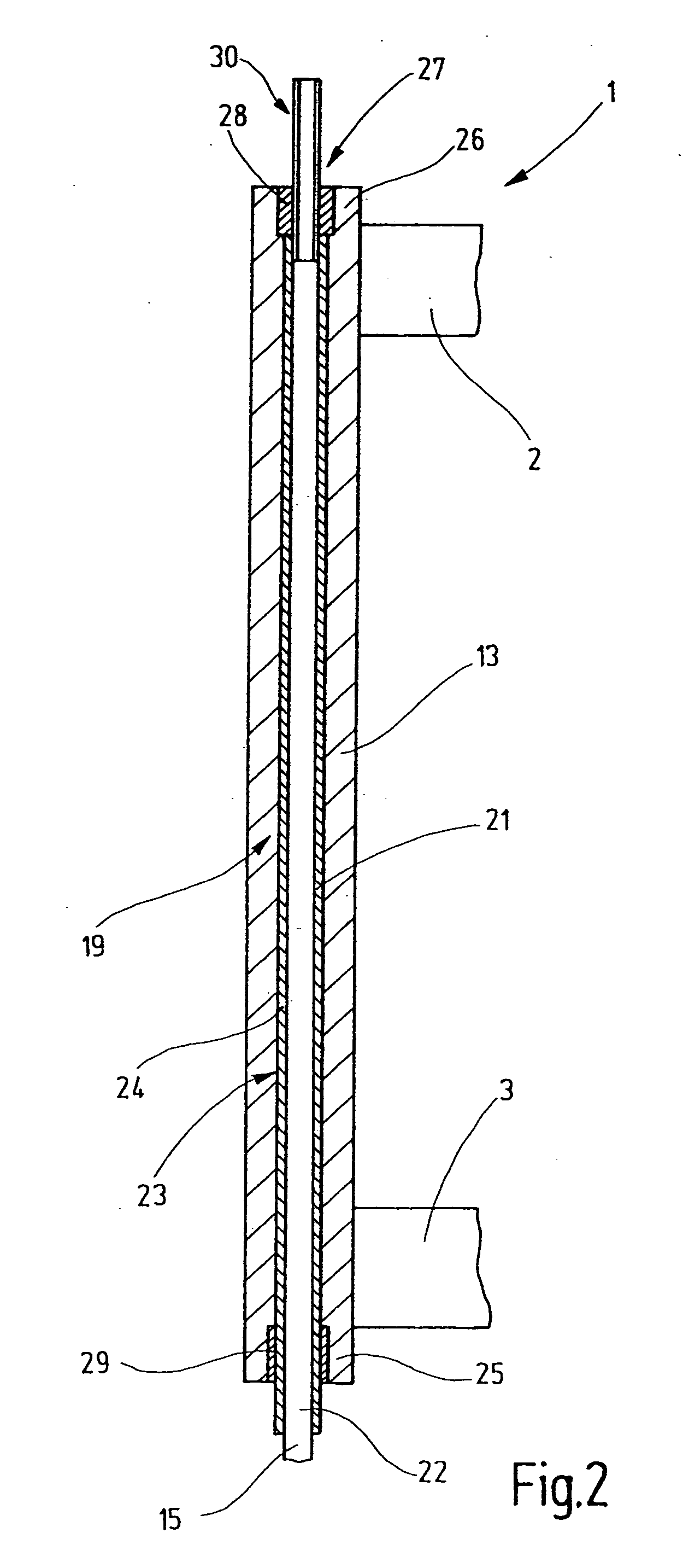
[0025] The frame rods 2, 3 are joined on their respective ends 8, 9, 11, 12 to lateral sampsons 13, 14, which in use are as a rule oriented vertically. The lateral sampsons 13, 14 with the frame rods 2, 3 form a rectangular frame. The lateral sampsons 13, 14 are guided longitudinally, or in other words in the present case vertically displaceably, either directly or via suitable guide means. To effect this driving motion, drive rods 15, 16 are provided, which extend through the lateral sampsons 13, 14. The drive rods 15, 16, with...


PUM


Abstract

A heddle frame (1) is driven via drive rods (15), which pass through its lateral sampsons (13). To that end, the lateral sampsons (13) each have a corresponding channel (19). The play between the circumferential face (22) of the drive rods (15) and the channel wall face (21) of the respective channel (19) has an intermediate layer (24), which extends over the full length, or portions, of the drive rod (15). The intermediate layer (24) preferably comprises an impact-proof, permanent-elastic, damping material. A slight residual play allows the introduction of the drive rods (15) and the intermediate layer (24) into the channel (19) without force.

Description

CROSS REFERENCE TO RELATED APPLICATION [0001] This application claims the priority of German Patent Application No. 10 2004 047 929.1, filed on Oct. 1, 2004, the subject matter of which, in its entirety, is incorporated herein by reference. FIELD OF THE INVENTION [0002] The invention relates to a heddle frame for a power loom. BACKGROUND OF THE INVENTION [0003] From European Patent Disclosure EP 0 520 540 A1, a heddle frame is known, having two frame rods, disposed horizontally at a spacing from one another, which are joined on their respective ends by a respective vertical lateral sampson. The lateral sampsons and the frame rods thus form a rectangular frame, called a heddle frame. Support rails on which heddles are seated are retained on the frame rods. Each heddle has an eyelet through which a warp yarn extends. Moving the entire heddle frame up and down opens or closes sheds into which weft yarns are to be inserted. Drive bars that extend all the way through the lateral sampsons...

Claims


Application Information

Patent Timeline
Patent Type & Authority Applications(United States)
IPC IPC(8): D03C9/00D03C1/14D03C9/06
CPCD03C9/065D03C9/0683
Inventor METTLER, FRANZ
Owner GROZ BECKERT KG
Why Eureka
Try Eureka